Installation and Operation, cont’d
step 1 to connect the computer to the interface. Set the front panel monitor ID bit DIP switches to On if no local monitor will be used.
5.Connect powered speakers or another audio device to the rear panel captive screw connector. Follow the wiring guide shown below. Insert the wires into the appropriate openings. Tighten the screws on top to fasten the wires, then insert the wired audio connector into the audio output connector on the interface rear panel.
Connect the sleeve to ground (GND). Connecting the sleeve to a negative
Mounted under
aDesk
Front
Rear
RGB 138xi
LBC w/ Audio
Cable
AC Power
Network
Connection
Audio
or
Sample Modular Connector Plates
Unbalanced Output
Tip
See Warning
Sleeve (s)
Tip
See Warning
Balanced Output
Tip
Ring
Sleeve (s)
Tip
Ring
Wiring captive screw connectors for audio output
6.Set the DIP and toggle switches. Use the “Front Panel” and “Rear Panel” sections of this chapter as a guide.
7.Connect power cords and turn on the devices in the following order: display and audio output devices (projectors, monitors, speakers), interface, and input device (computer).
Power
2 - BNC
2 - RCA
2 -
2 - F Connectors
Front
Rear
RGB 158xi
MonitorProjector
2 - 3.5mm Stereo mini
DB9
HD15
1 -
Rack Mounted
or
Mounted under
a Desk
AC Power
Network
Connection
Audio
Monitor
or
The system is now ready for operation.
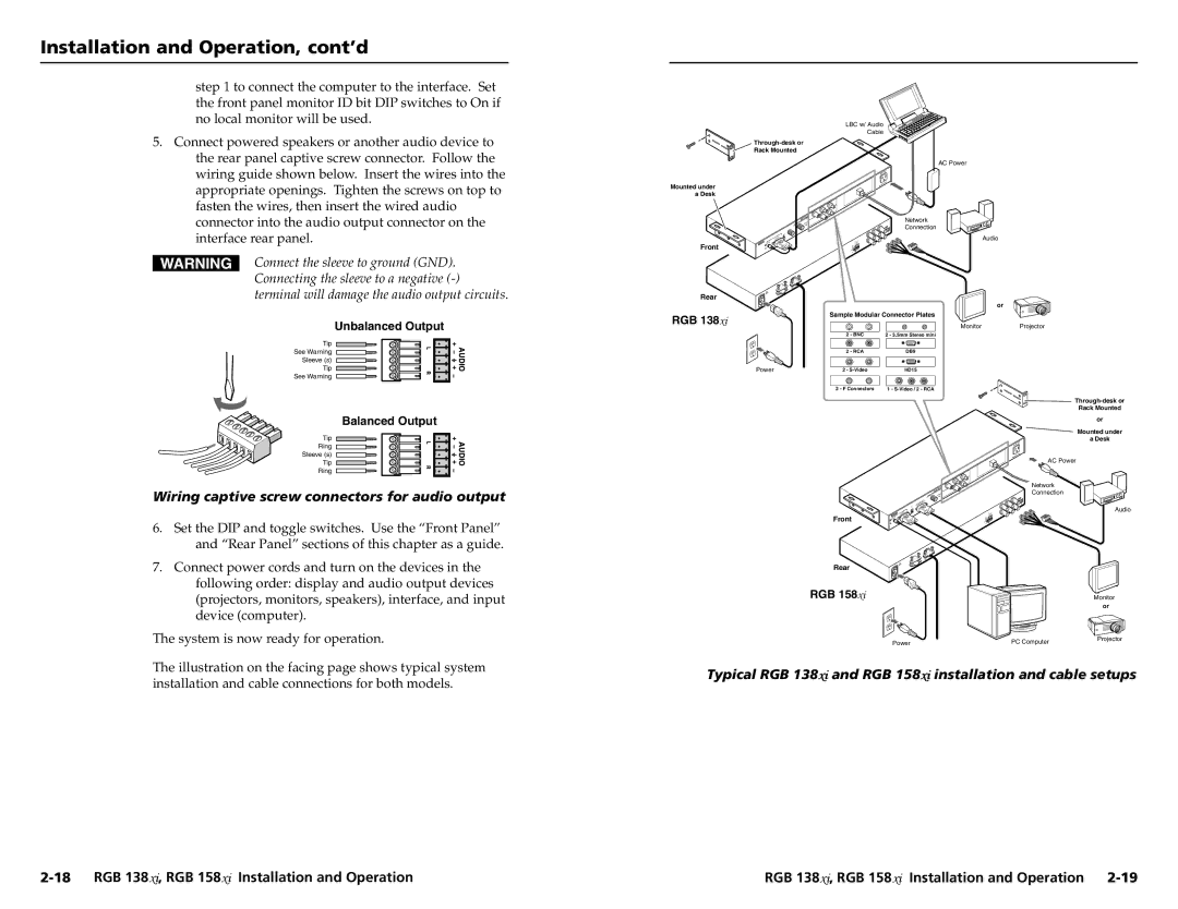
The illustration on the facing page shows typical system installation and cable connections for both models.
Power | PC Computer | Projector |
|
Typical RGB 138xiand RGB 158xiinstallation and cable setups
RGB 138xi, RGB 158xi Installation and Operation |