Installation and Operation
Installation Overview
This is an overview of the installation process. You will find detailed installation instructions in this chapter.
To install and set up the RGB 138xi or RGB 158xi for operation, follow these basic steps:
1 Turn all of the equipment off. Make sure that the |
computer, the interface and the output device(s) |
(projector or display monitor, and local monitor) are |
Front Panels
This section will familiarize you with the front panel features and the options for making connections and changing settings.
Setting DIP switches
The DIP switches on the front panel of the RGB 158xi and on the rear panels of the RGB 138xi and the RGB 158xi may be either the rocking type or the sliding type.
| all turned off and disconnected from the power |
| source. |
| Set internal jumpers for sync polarity and sync pulse |
2 | |
| width. See “Setting Internal Jumpers” in this chapter. |
| Install optional adapter plates for |
3 | |
| connections. See “Installing Adapter Plates” in this |
| chapter. |
1 | 2 | 3 | 4 |
1 | 2 | 3 | 4 |
To set rocking type DIP switches, use a small screwdriver to depress the appropriate end of each switch.
To set sliding type DIP switches, use a small screwdriver to slide (push) the switch to the On/closed or Off/open position.
4 | Install the rubber feet for tabletop use, or install the |
| appropriate brackets and furniture or rack mount the |
| interface. See “Mounting the Interfaces” in this |
| chapter. |
5 | Attach the input (computer) and output (display, |
| local monitor and audio) cables. See “Cabling” in |
| this chapter. |
6 | Set the DIP and toggle switches. Use the “Front |
| Panels” and “Rear Panels” sections of this chapter as |
| a guide. |
7 | Connect power cords and turn on the devices in the |
| following order: output devices (projector, monitors, |
| speakers) and input device (computer). |
8 | The image should now appear on screen, and sound |
| should be audible. If not, ensure that all devices are |
| plugged in and receiving power. Check the cabling |
| and switch settings, and make adjustments as |
| needed. |
| Refer to “Troubleshooting” in this chapter, then call |
| Extron’s customer support hotline, if needed. |
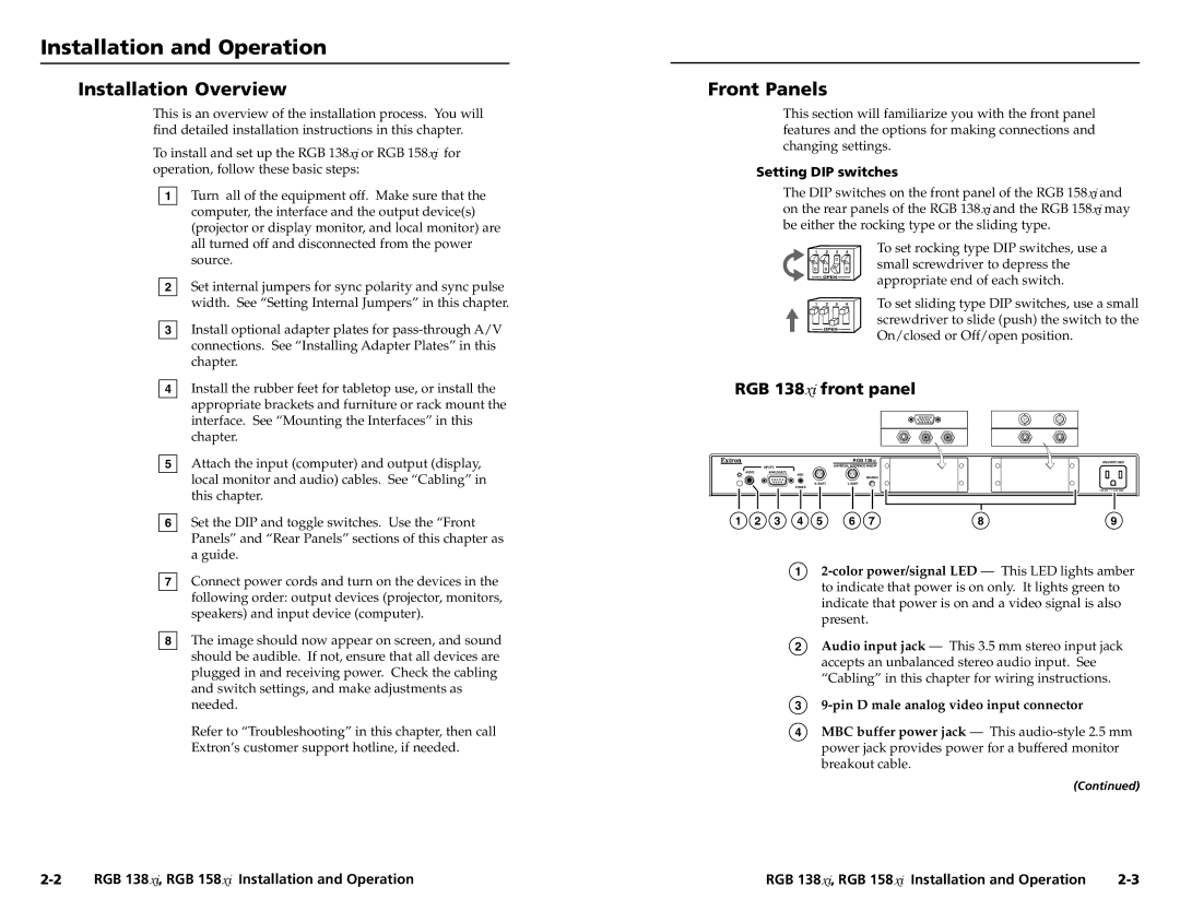
RGB 138xi front panel
| RGB 138 | UNSWITCHED |
INPUTS | UNIVERSAL INTERFACE W/ADSP |
|
AUDIOANALOG/ECL
MBC
| MIN/MAX |
H. SHIFT | V. SHIFT |
POWER | |
|
1 | 2 | 3 | 4 | 5 | 6 | 7 | 8 | 9 |
1
2Audio input jack — This 3.5 mm stereo input jack accepts an unbalanced stereo audio input. See “Cabling” in this chapter for wiring instructions.
39-pin D male analog video input connector
4MBC buffer power jack — This
(Continued)
RGB 138xi, RGB 158xi Installation and Operation | RGB 138xi, RGB 158xi Installation and Operation |