Installation and Operation, cont’d
Adapter plates should be attached to the output cables and interface before the interface is installed in a rack or in furniture. The screws for installing the adapter plates are built into the plates, so no additional screws will be needed.
Adapter plate installation must be performed by authorized service personnel only.
Follow these steps to install adapter plates. The RGB 138xi is shown for illustration, but the steps apply to both models.
1.Make sure that the power is removed from the interface by disconnecting the AC power cord from the unit.
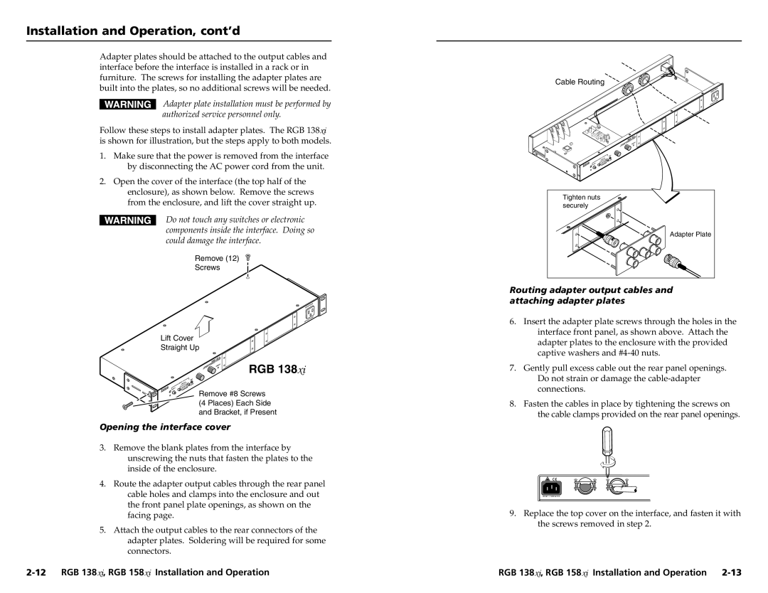
2.Open the cover of the interface (the top half of the enclosure), as shown below. Remove the screws from the enclosure, and lift the cover straight up.
Do not touch any switches or electronic components inside the interface. Doing so could damage the interface.
Remove (12)
Screws
|
| ITC | HED | |
UN | SW |
|
| |
|
|
|
| |
|
| TS | MA | X. |
| WAT |
|
| |
600 |
|
|
| |
|
|
|
| |
Lift Cover
Straight Up
|
|
|
|
|
|
|
| 13 | 8 x | i |
|
|
|
|
|
|
| GB | DSP |
| |||
|
|
|
|
|
| W /A |
|
|
| ||
|
|
|
|
|
| R | CE |
|
|
| RGB 138xi |
|
|
|
|
| AL IN | TERFA |
|
| AX | ||
|
|
|
| ERS |
|
| IN/M |
| |||
|
|
| UNIV |
|
|
| M |
|
| ||
|
|
|
|
|
|
|
|
|
| ||
|
|
|
|
|
|
|
|
|
|
| |
|
| MBC |
|
|
|
|
|
|
|
| |
| PUTS | OG | ER |
|
|
|
|
|
|
|
|
| IN ANAL | POW |
|
|
|
|
|
|
|
| |
|
|
|
|
|
|
|
|
|
|
| |
AUD | IO |
|
|
|
|
|
|
|
|
|
|
|
|
|
|
|
|
|
|
|
|
| |
Remove #8 Screws (4 Places) Each Side and Bracket, if Present
Opening the interface cover
3.Remove the blank plates from the interface by unscrewing the nuts that fasten the plates to the inside of the enclosure.
4.Route the adapter output cables through the rear panel cable holes and clamps into the enclosure and out the front panel plate openings, as shown on the facing page.
5.Attach the output cables to the rear connectors of the adapter plates. Soldering will be required for some
connectors.
Cable Routing
UNSWITCHED
. MAX WATTS 600
xi 138
RGB
Tighten nuts |
securely |
Adapter Plate |
Routing adapter output cables and attaching adapter plates
6.Insert the adapter plate screws through the holes in the interface front panel, as shown above. Attach the adapter plates to the enclosure with the provided captive washers and
7.Gently pull excess cable out the rear panel openings. Do not strain or damage the
8.Fasten the cables in place by tightening the screws on the cable clamps provided on the rear panel openings.
![]() 50/60 Hz 0.5A
50/60 Hz 0.5A
9. Replace the top cover on the interface, and fasten it with the screws removed in step 2.
RGB 138xi, RGB 158xi Installation and Operation |