Installation and Operation, cont’d
5Horizontal shift control knob — This control adjusts the horizontal centering of the remote output display.
The horizontal and vertical shift controls have no mechanical limits to rotation. When the minimum or maximum limit of the control is reached, the picture will cease to move on screen, and the MIN/MAX indicator LED will light red.
If the DDSP™ DIP switch is set to On, the horizontal and vertical shift controls are disabled.
6Vertical shift control knob — This control adjusts the vertical centering of the remote output display. See the notes above for horizontal shift control.
7MIN/MAX indicator LED — This LED lights red whenever the lower or upper limits of the horizontal or vertical shift controls are reached.
8Optional architectural adapter plates — Up to four adapter plates for
9AC power output connector — An unswitched standard IEC AC power connector lets you connect a peripheral device that requires power. This feature is not available in Europe.
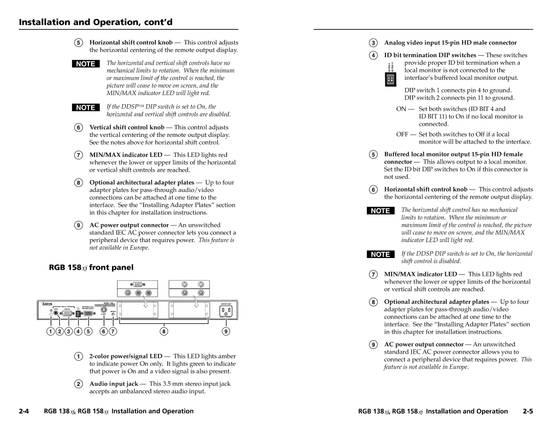
RGB 158xi front panel
RGB 158 | UNSWITCHED |
| INPUTS | 4 | 11 | BUFFERED LOCAL UNIVERSAL INTERFACE W/ADSP |
AUDIO | ANALOG | PIN | PIN | MONITOR OUTPUT |
|
| ID | ID | MIN/MAX |
|
|
|
| |
|
|
|
| H. SHIFT |
![]() 0.5A MAX.
0.5A MAX.
1 | 2 | 3 | 4 | 5 | 6 | 7 | 8 | 9 |
1
2Audio input jack — This 3.5 mm stereo input jack
accepts an unbalanced stereo audio input.
3 Analog video input
4 ID bit termination DIP switches — These switches
4 | 11 | provide proper ID bit termination when a |
ID PIN | ID PIN | local monitor is not connected to the |
|
|
interface’s buffered local monitor output.
DIP switch 1 connects pin 4 to ground.
DIP switch 2 connects pin 11 to ground.
ON — Set both switches (ID BIT 4 and
ID BIT 11) to On if no local monitor is connected.
OFF — Set both switches to Off if a local monitor will be attached to the interface.
5Buffered local monitor output
6Horizontal shift control knob — This control adjusts the horizontal centering of the remote output display.
The horizontal shift control has no mechanical limits to rotation. When the minimum or maximum limit of the control is reached, the picture will cease to move on screen, and the MIN/MAX indicator LED will light red.
If the DDSP DIP switch is set to On, the horizontal shift control is disabled.
7MIN/MAX indicator LED — This LED lights red whenever the lower or upper limits of the horizontal or vertical shift controls are reached.
8Optional architectural adapter plates — Up to four adapter plates for
9AC power output connector — An unswitched standard IEC AC power connector allows you to connect a peripheral device that requires power. This feature is not available in Europe.
RGB 138xi, RGB 158xi Installation and Operation | RGB 138xi, RGB 158xi Installation and Operation |