Installation and Operation, cont’d
4 — DDSP
DDSP disables all sync processing. This feature may be necessary for digital display devices such as LCD, DLP (digital light processor) and plasma displays. Use this option if the image is not displayed properly after other options, such as serration pulse and video termination changes, have been tried.
On — The interface uses DDSP, which does not process the sync signal.
DDSP disables the horizontal and vertical centering controls.
Off — The interface performs sync processing operations.
5 — No monitor (ID bit termination) — This switch controls the input assigned to the local monitor output and ID bit termination.
On — ID bits 4 and 11 are tied to ground.
Off — ID bits 4 and 11 are unterminated.
6 — Mono audio output (RGB 192 only, spare on RGB 190F)
On — Monaural audio is output on the left channel only. When mono is selected, the right and left inputs are combined and placed on the left output connectors.
Off — Normal stereo output.
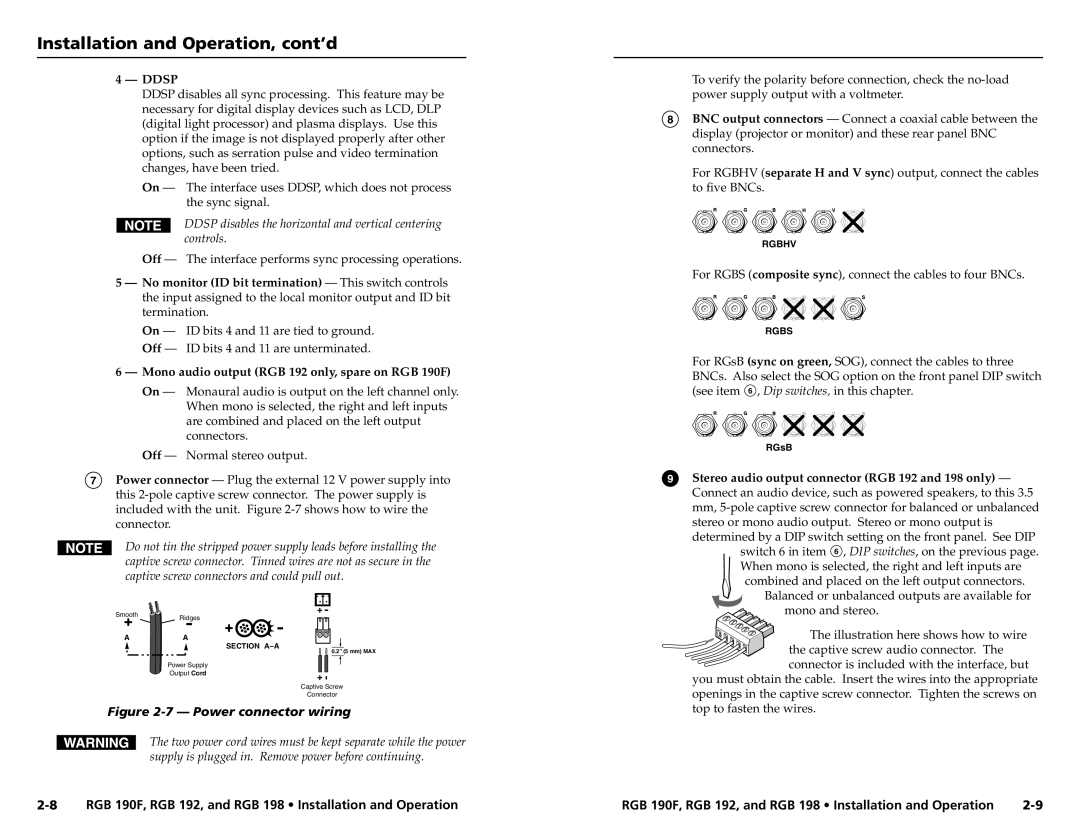
7Power connector — Plug the external 12 V power supply into this
Do not tin the stripped power supply leads before installing the captive screw connector. Tinned wires are not as secure in the captive screw connectors and could pull out.
SmoothRidges
A | A |
SECTION
0.2” (5 mm) MAX
Power Supply
Output Cord
Captive Screw
Connector
Figure 2-7 — Power connector wiring
The two power cord wires must be kept separate while the power supply is plugged in. Remove power before continuing.
To verify the polarity before connection, check the
8BNC output connectors — Connect a coaxial cable between the display (projector or monitor) and these rear panel BNC connectors.
For RGBHV (separate H and V sync) output, connect the cables to five BNCs.
RGBHV
For RGBS (composite sync), connect the cables to four BNCs.
RGBS
For RGsB (sync on green, SOG), connect the cables to three BNCs. Also select the SOG option on the front panel DIP switch (see item 6 , Dip switches, in this chapter.
RGsB
9Stereo audio output connector (RGB 192 and 198 only) — Connect an audio device, such as powered speakers, to this 3.5 mm,
switch 6 in item 6 , DIP switches, on the previous page.
When mono is selected, the right and left inputs are combined and placed on the left output connectors.
Balanced or unbalanced outputs are available for mono and stereo.
The illustration here shows how to wire
the captive screw audio connector. The connector is included with the interface, but
you must obtain the cable. Insert the wires into the appropriate openings in the captive screw connector. Tighten the screws on top to fasten the wires.
RGB 190F, RGB 192, and RGB 198 • Installation and Operation | RGB 190F, RGB 192, and RGB 198 • Installation and Operation |