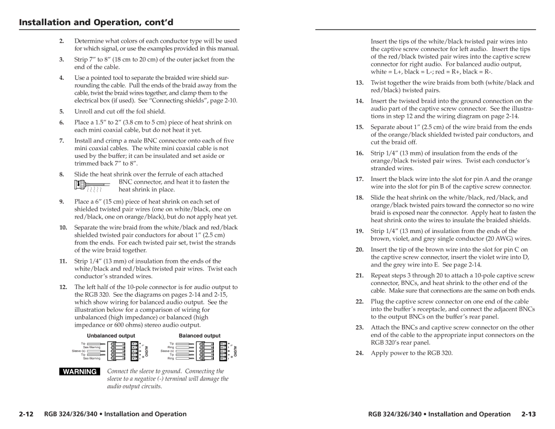
RGB 324, RGB 326, RGB 340 specifications
Extron Electronics is a renowned manufacturer known for its extensive range of innovative products in the realm of audiovisual integration. Among their impressive lineup are the RGB 326, RGB 340, and RGB 324 models, which stand out due to their exceptional features and cutting-edge technologies tailored for high-performance video applications.The Extron RGB 326 is a versatile, high-resolution RGBHV and video line amplifier designed to enhance the quality of analog video signals. One of its main features is the capability to support resolutions up to 1920x1200, ensuring compatibility with a wide range of display devices. It incorporates advanced circuitry that optimizes signal quality, reducing distortion and maintaining clarity over extended distances. This model also offers multiple outputs, allowing the simultaneous connection of multiple devices, which is ideal for complex installations.
The RGB 340 takes the functionality of video amplification a notch higher with its integrated digital processing capabilities. It provides features like automatic signal detection and adaptive equalization, which ensures optimal signal integrity, regardless of the input source or distance involved. The RGB 340 can also support a variety of input formats, including RGBHV, component video, and composite video, making it an excellent choice for diverse audiovisual setups. Additionally, built-in status LEDs allow users to monitor operational signals and quickly identify any potential issues.
On the other hand, the Extron RGB 324 is a compact yet powerful solution designed specifically for applications requiring a straightforward line amplifier with fewer connections. It boasts a user-friendly interface and a low-profile design, which makes it suitable for installations where space is limited. Like its counterparts, the RGB 324 also maintains high signal fidelity and can handle resolutions up to 1920x1200.
Another significant characteristic shared among these models is the robust build quality that Extron is known for. Designed for durability and reliability, they come with enhanced thermal management, ensuring long-term performance even in demanding environments. Furthermore, all models feature Extron's patented technology for optimal video performance, resulting in high-quality output with minimal signal degradation.
In summary, the Extron RGB 326, RGB 340, and RGB 324 exemplify the brand's commitment to delivering top-tier solutions for video signal management. Their innovative technologies and features make them indispensable tools for audiovisual integrators looking to achieve pristine image quality and reliability in their installations.

