SW2 DP specifications
The Extron SW2 DP is a state-of-the-art 2x1 DisplayPort switcher designed to facilitate seamless switching between two DisplayPort sources for a single DisplayPort display. This compact and versatile device is particularly useful in environments like classrooms, conference rooms, and and digital signage applications where multiple video sources need to be connected to a singular output.One of the standout features of the SW2 DP is its ability to support high-resolution video signals, delivering crisp video quality at resolutions up to 4K at 60Hz. This ensures that users can enjoy stunning visuals without any degradation in quality, making it ideal for high-performance tasks such as presentations, video conferences, and graphic design.
The SW2 DP is built with advanced digital switching technology that guarantees fast and reliable source switching, which reduces the latency often associated with traditional switching methods. This ensures that users do not experience interruptions while switching between sources, maintaining a smooth and professional flow during presentations.
It also incorporates Extron's exclusive EDID Minder technology. This feature manages the communication between the source and the display, ensuring that optimal video parameters are always set for the connected devices, which is essential for maintaining quality visuals over HDMI or DisplayPort connections.
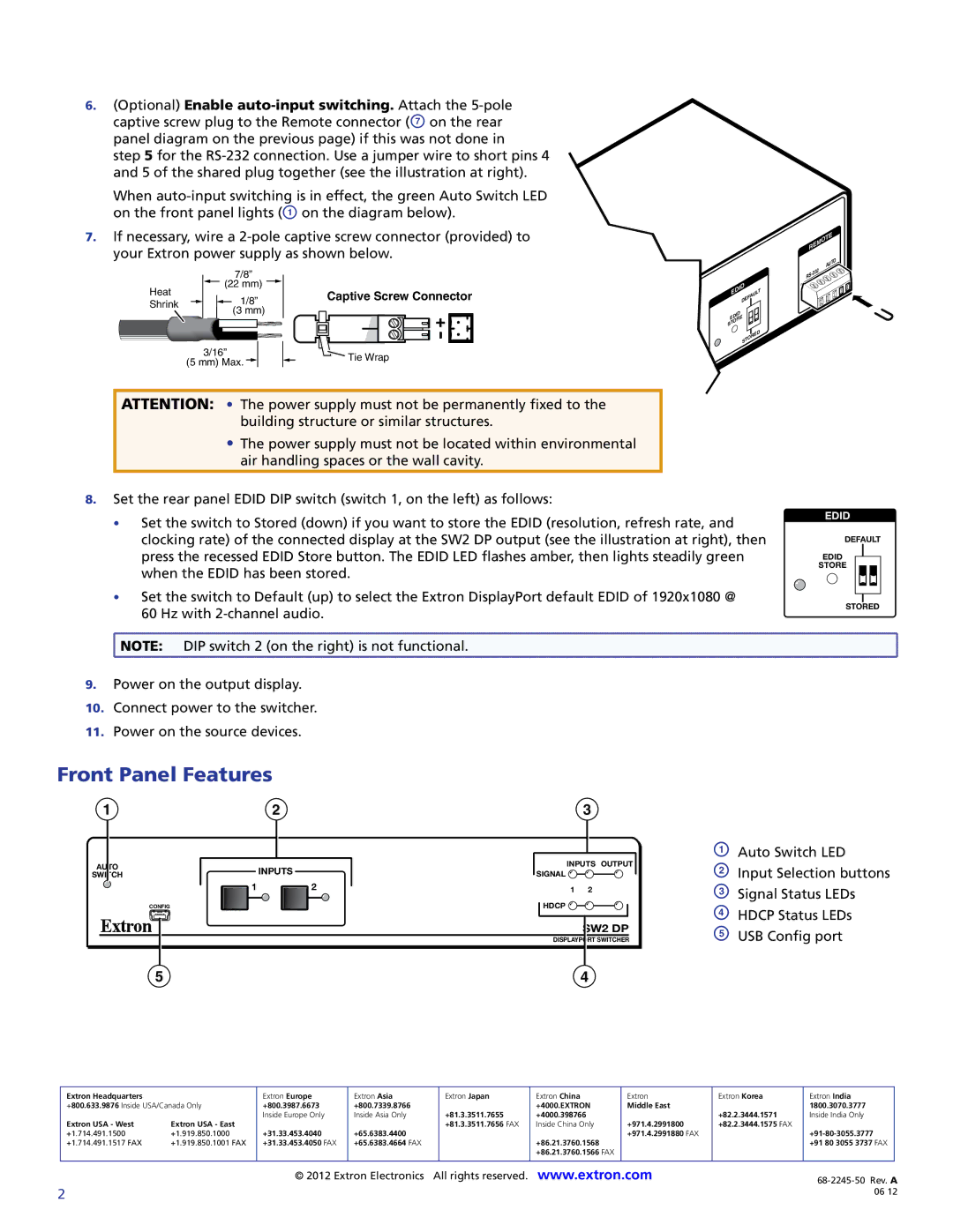
The device is designed for ease of use, with a user-friendly interface that includes front-panel buttons for manual source selection. In addition, the SW2 DP is equipped with an RS-232 port, allowing for integration with third-party control systems. This facilitates remote control and automation, fitting seamlessly into existing AV setups.
Moreover, the SW2 DP is compatible with the Extron's extensive range of other AV components, showcasing its flexibility within a broader AV system architecture. With robust construction and reliable performance, the SW2 DP stands out as a vital component for any professional or educational setting requiring versatile video source management.
In summary, the Extron SW2 DP DisplayPort switcher offers a combination of high performance, advanced features, and seamless integration options. Its ability to handle high-resolution signals while providing reliable switching makes it an essential tool for anyone looking to enhance their AV experience. Whether for education, video conferencing, or digital signage, the SW2 DP meets the demands of modern AV applications effectively.

