TLP 1000MV and TLP 1000TV • Setup Guide
Overview
|
|
|
|
|
|
|
| : |
|
|
|
|
|
|
|
| ANT |
| for |
| |||
|
|
|
| T |
|
| .com |
| |||
|
|
|
|
|
|
|
| ||||
| IMPOR. |
| on | Series |
| ||||||
|
|
| extr |
|
| ||||||
|
| towww |
|
|
| 1000 |
|
| . | ||
|
|
|
|
|
| connecting | |||||
Refer |
| TLP |
|
|
| ce | |||||
|
|
|
| e |
| sour |
| ||||
| completebefor |
|
|
|
|
| |||||
the guide | thepower |
|
| ||||||||
user |
| to |
|
|
|
|
|
|
|
| |
the | product |
|
|
|
|
|
|
|
|
| |
|
|
|
|
|
|
|
|
|
|
| |
The Extron TLP 1000MV
These touchpanels communicate through an Ethernet connection to a configurable IP Link control processor. Video and audio input is provided by a twisted pair cable connected to an MTP transmitter.
![]() NOTE: The network output must be connected to a network switch, hub, or router that is connected to an Ethernet
NOTE: The network output must be connected to a network switch, hub, or router that is connected to an Ethernet
LAN or the Internet. An Extron IP Link controller must also be connected to the same network. Suggested models include IPL T S series (for example, IPL T S4), IPL 250, IPL T CR48, IPL T SFI244, or IPCP 505.
Extron strongly recommends that power is provided by a Power over Ethernet (PoE) power supply.
This guide provides basic instructions for experienced installers to mount and perform initial configuration on the
TLP 1000 series of touchpanels. Full instructions and reference material can be found in the TLP 1000MV and TLP 1000TV User Guide, which is available on the Extron website (www.extron.com).
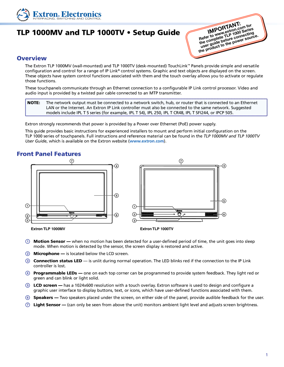
Front Panel Features
7 | 7 |
4
| 5 |
|
1 |
| 1 |
|
| |
2 | 6 | 2 |
|
| |
3 |
| 3 |
4
5
6
Extron TLP 1000MV | Extron TLP 1000TV |
AMotion Sensor — when no motion has been detected for a
BMicrophone — is located below the LCD screen.
CConnection status LED — is unlit during normal operation. The LED blinks red if the connection to the IP Link controller is lost.
DProgrammable LEDs — one on each top corner can be programmed to provide system feedback. They light red or green and can blink or light solid.
ELCD screen — has a 1024x600 resolution with a touch overlay. Extron software is used to design and configure a graphic user interface to display buttons, text, or icons, which have user‑defined functions associated with them.
FSpeakers — Two speakers placed under the screen, on either side of the panel, provide audible feedback for the user.
GLight Sensor — (can only be seen from above the unit) monitors ambient light level and adjusts screen brightness.
1