Installation
Installing the V-Lock™ Assembly Kit
If your speakers are not already installed, follow the instructions outlined in the SI 3 User's Guide supplied with the speakers (or online at www.extron.com).
If your speakers are already installed, replace the
NReferring to packaging information for location, carefully remove and check contents before installation.
NExtron recommends that the wiring installation is performed by a professional audio equipment installer.
NFor speaker details, specifications, troubleshooting tips, and service access information, refer to the
SI 3 User's Guide supplied with the speakers, or online at www.extron.com.
Existing wall mounting application
To replace a damaged
1. | Remove the Extron logo from the front of the speaker to |
| access the hex cap screw. Retain the logo. |
2. | Insert the hex tool and unlock the speaker. |
3. | Carefully lift the speakers away from the bracket, then |
| disconnect the seismic cable and audio wires from the rear |
| of the speakers. |
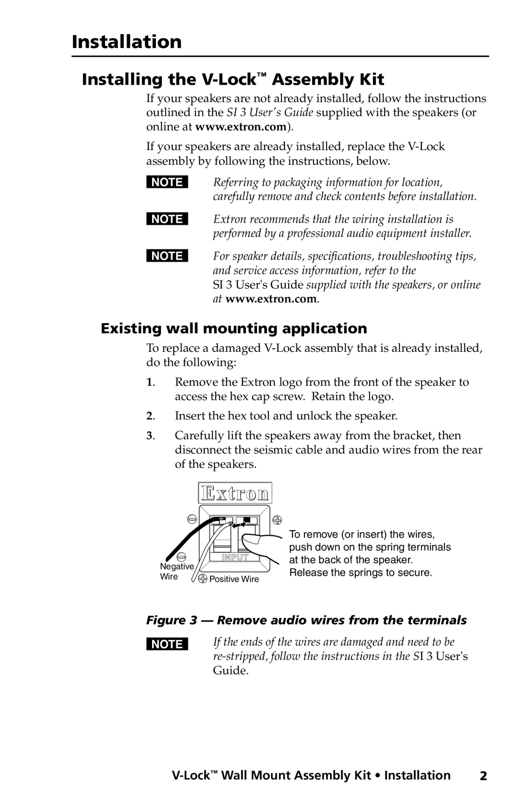
Negative | INPUT |
| |
Wire | Positive Wire |
To remove (or insert) the wires, push down on the spring terminals at the back of the speaker. Release the springs to secure.
Figure 3 — Remove audio wires from the terminals
NIf the ends of the wires are damaged and need to be
2 |