VSC 150 specifications
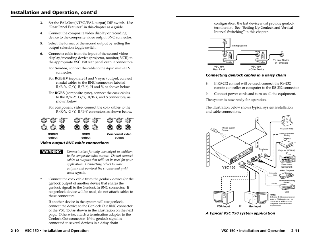
The Extron VSC 150 is a versatile video scaling and conversion device designed for professional audio-visual applications. It is particularly well-suited for environments requiring high-quality image processing and flexible video interfacing. With its array of features and advanced technologies, the VSC 150 stands out as a reliable solution for various AV setups, including classrooms, conference rooms, and large venues.One of the key features of the VSC 150 is its high-performance video scaling technology. It offers up to 16 different output resolutions, allowing users to adapt video signals to meet the specific needs of different display devices. This flexibility ensures that content is delivered in the optimal resolution for every environment, enhancing the overall viewing experience. The device supports a wide variety of input formats, including composite video, S-video, and component video, ensuring compatibility with legacy equipment as well as contemporary digital sources.
The VSC 150 also incorporates advanced signal processing capabilities. It includes features such as video noise reduction, dynamic range control, and edge enhancement. These technologies work in unison to improve image quality, providing sharp, clear visuals that are critical in professional settings. The built-in image freeze and zoom functions further enhance the user experience, allowing for focused presentations without losing attention.
Another notable characteristic of the VSC 150 is its user-friendly interface. The device features an easy-to-navigate front panel, complete with LED indicators for quick status monitoring. Additionally, it can be controlled remotely via Ethernet or RS-232, providing flexibility in larger setups where direct access may be limited. The integration into control systems is seamless, making it a popular choice for custom AV installations.
In terms of audio capabilities, the VSC 150 can handle both analog and digital audio signals, ensuring that users can maintain high-quality audio alongside video content. It also features audio embedding and de-embedding options, which facilitate integration with various audio systems.
Overall, the Extron VSC 150 is a powerful and sophisticated video scaler that combines excellent performance, robust features, and ease of use. It is an ideal choice for professionals seeking a reliable solution for managing video content in diverse AV environments, effectively meeting the demands of modern presentations and displays. With the VSC 150, users can achieve impressive results, ensuring that their visual communications stand out.

