Connecting the VTG Output Cables
RGB Output (BNC, Analog)
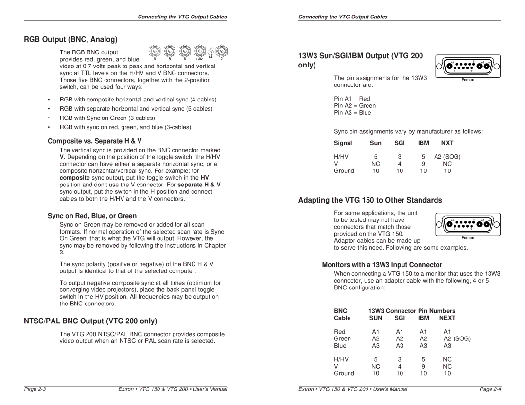
The RGB BNC output![]()
![]() provides red, green, and blue
provides red, green, and blue ![]()
![]()
![]()
![]()
![]()
![]()
![]() video at 0.7 volts peak to peak and horizontal and vertical sync at TTL levels on the H/HV and V BNC connectors. Those five BNC connectors, together with the
video at 0.7 volts peak to peak and horizontal and vertical sync at TTL levels on the H/HV and V BNC connectors. Those five BNC connectors, together with the
•RGB with composite horizontal and vertical sync
•RGB with separate horizontal and vertical sync
•RGB with Sync on Green
•RGB with sync on red, green, and blue
Composite vs. Separate H & V
The vertical sync is provided on the BNC connector marked V. Depending on the position of the toggle switch, the H/HV connector can have either a separate horizontal sync, or a composite horizontal/vertical sync. For example: for composite sync output, put the toggle switch in the HV position and don't use the V connector. Forseparate H & V sync output, put the switch in the H position and connect cables to both the H/HV and the V connectors.
Sync on Red, Blue, or Green
Sync on Green may be removed or added for all scan formats. If normal operation of the selected scan rate is Sync On Green, that is what the VTG will output. However, the sync may be removed by following the instructions in Chapter 3.
The sync polarity (positive or negative) of the BNC H & V output is identical to that of the selected computer.
To output negative composite sync at all times (optimum for converging video projectors), place the back panel toggle switch in the HV position. All frequencies may be output on the BNC connectors.
NTSC/PAL BNC Output (VTG 200 only)
The VTG 200 NTSC/PAL BNC connector provides composite video output when an NTSC or PAL scan rate is selected.
Connecting the VTG Output Cables
13W3 Sun/SGI/IBM Output (VTG 200 only)
The pin assignments for the 13W3 connector are:
Pin A1 = Red
Pin A2 = Green
Pin A3 = Blue
Sync pin assignments vary by manufacturer as follows:
Signal | Sun | SGI | IBM | NXT |
H/HV | 5 | 3 | 5 | A2 (SOG) |
V | NC | 4 | 9 | NC |
Ground | 10 | 10 | 10 | 10 |
Adapting the VTG 150 to Other Standards
For some applications, the unit
to be tested may not have connectors that match those provided on the VTG 150.
Adaptor cables can be made up
to serve this need. Following are some examples.
Monitors with a 13W3 Input Connector
When connecting a VTG 150 to a monitor that uses the 13W3 connector, use an adapter cable with the following, 4 or 5 BNC configuration:
BNC | 13W3 Connector Pin Numbers | |||
Cable | SUN | SGI | IBM | NEXT |
Red | A1 | A1 | A1 | A1 |
Green | A2 | A2 | A2 | A2 (SOG) |
Blue | A3 | A3 | A3 | A3 |
H/HV | 5 | 3 | 5 | NC |
V | NC | 4 | 9 | NC |
Ground | 10 | 10 | 10 | 10 |
Page | Extron • VTG 150 & VTG 200 • User’s Manual | Extron • VTG 150 & VTG 200 • User’s Manual | Page |