Connecting the VTG Output Cables
Connecting the VTG Output Cables
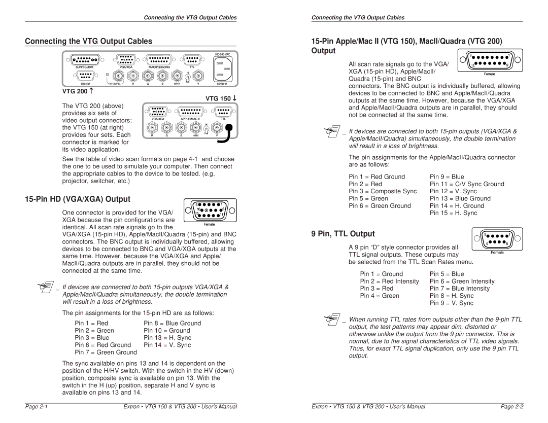
VTG 200 ↑
VTG 150 ↓
The VTG 200 (above) provides six sets of video output connectors; the VTG 150 (at right) provides four sets. Each connector is marked for its video application.
See the table of video scan formats on page
15-Pin HD (VGA/XGA) Output
One connector is provided for the VGA/ XGA because the pin configurations are
identical. All scan rate signals go to the
VGA/XGA
_ If devices are connected to both
The pin assignments for the
Pin 1 = Red | Pin 8 = Blue Ground | ||
Pin 2 | = Green | Pin 10 | = Ground |
Pin 3 | = Blue | Pin 13 = H. Sync | |
Pin 6 | = Red Ground | Pin 14 | = V. Sync |
Pin 7 | = Green Ground |
|
|
The sync available on pins 13 and 14 is dependent on the position of the H/HV switch. With the switch in the HV (down) position, composite sync is available on pin 13. With the switch in the H (up) position, separate H and V sync is available on pins 13 and 14.
Connecting the VTG Output Cables
15-Pin Apple/Mac II (VTG 150), MacII/Quadra (VTG 200) Output
All scan rate signals go to the VGA/ XGA
Quadra
connectors. The BNC output is individually buffered, allowing devices to be connected to BNC and Apple/MacII/Quadra outputs at the same time. However, because the VGA/XGA and Apple/MacII/Quadra outputs are in parallel, they should not be connected at the same time.
_ If devices are connected to both
The pin assignments for the Apple/MacII/Quadra connector are as follows:
Pin 1 = Red Ground | Pin 9 = Blue | ||
Pin 2 | = Red | Pin 11 | = C/V Sync Ground |
Pin 3 = Composite Sync | Pin 12 | = V. Sync | |
Pin 5 | = Green | Pin 13 = Blue Ground | |
Pin 6 | = Green Ground | Pin 14 | = H. Ground |
|
| Pin 15 | = H. Sync |
9 Pin, TTL Output
A 9 pin “D” style connector provides all TTL signal outputs. These outputs may
be selected from the TTL Scan Rates menu.
Pin 1 | = Ground | Pin 5 = Blue | |
Pin 2 = Red Intensity | Pin 6 | = Green Intensity | |
Pin 3 | = Red | Pin 7 | = Blue Intensity |
Pin 4 | = Green | Pin 8 = H. Sync | |
|
| Pin 9 = V. Sync | |
_ When running TTL rates from outputs other than the
Page | Extron • VTG 150 & VTG 200 • User’s Manual | Extron • VTG 150 & VTG 200 • User’s Manual | Page |