Operating the Video Test Generator
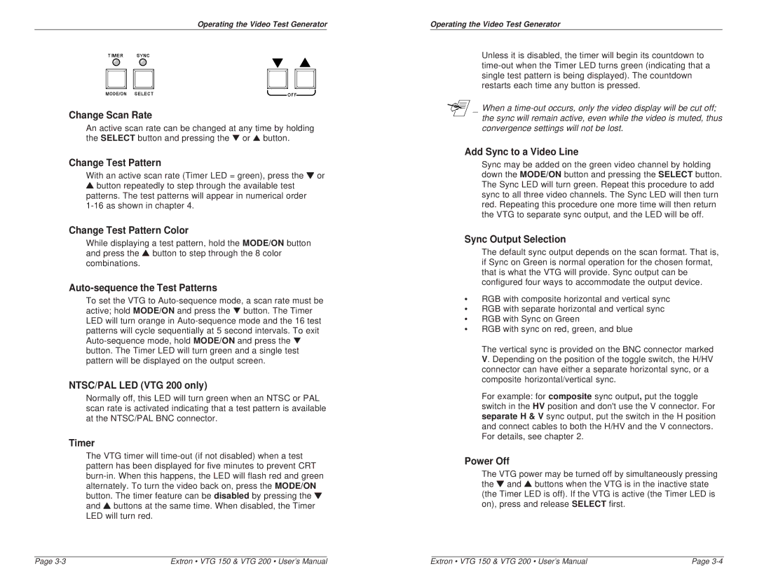
Change Scan Rate
An active scan rate can be changed at any time by holding the SELECT button and pressing the ▼ or ▲ button.
Change Test Pattern
With an active scan rate (Timer LED = green), press the ▼ or
▲button repeatedly to step through the available test patterns. The test patterns will appear in numerical order
Change Test Pattern Color
While displaying a test pattern, hold the MODE/ON button and press the ▲ button to step through the 8 color combinations.
Auto-sequence the Test Patterns
To set the VTG to
NTSC/PAL LED (VTG 200 only)
Normally off, this LED will turn green when an NTSC or PAL scan rate is activated indicating that a test pattern is available at the NTSC/PAL BNC connector.
Timer
The VTG timer will
Operating the Video Test Generator
Unless it is disabled, the timer will begin its countdown to
_ When a
Add Sync to a Video Line
Sync may be added on the green video channel by holding down the MODE/ON button and pressing the SELECT button. The Sync LED will turn green. Repeat this procedure to add sync to all three video channels. The Sync LED will then turn red. Repeating this procedure one more time will then return the VTG to separate sync output, and the LED will be off.
Sync Output Selection
The default sync output depends on the scan format. That is, if Sync on Green is normal operation for the chosen format, that is what the VTG will provide. Sync output can be configured four ways to accommodate the output device.
•RGB with composite horizontal and vertical sync
•RGB with separate horizontal and vertical sync
•RGB with Sync on Green
•RGB with sync on red, green, and blue
The vertical sync is provided on the BNC connector marked V. Depending on the position of the toggle switch, the H/HV connector can have either a separate horizontal sync, or a composite horizontal/vertical sync.
For example: for composite sync output, put the toggle switch in the HV position and don't use the V connector. For separate H & V sync output, put the switch in the H position and connect cables to both the H/HV and the V connectors. For details, see chapter 2.
Power Off
The VTG power may be turned off by simultaneously pressing the ▼ and ▲ buttons when the VTG is in the inactive state (the Timer LED is off). If the VTG is active (the Timer LED is on), press and release SELECT first.
Page | Extron • VTG 150 & VTG 200 • User’s Manual | Extron • VTG 150 & VTG 200 • User’s Manual | Page |