ATTENTION
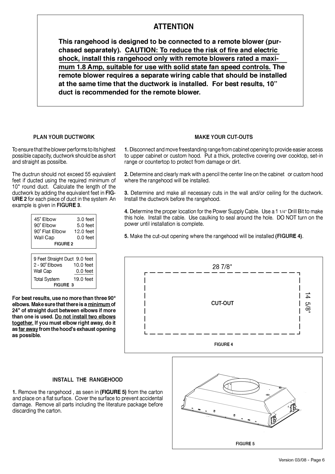
This rangehood is designed to be connected to a remote blower (pur- chased separately). CAUTION: To reduce the risk of fire and electric shock, install this rangehood only with remote blowers rated a maxi- mum 1.8 Amp, suitable for use with solid state fan speed controls. The remote blower requires a separate wiring cable that should be installed at the same time that the ductwork is installed. For best results, 10” duct is recommended for the remote blower.
PLAN YOUR DUCTWORK
To ensure that the blower performs to its highest possible capacity, ductwork should be as short and straight as possilbe.
The ductrun should not exceed 55 equivalent feet if ducted using the required minimum of 10" round duct. Calculate the length of the ductwork by adding the equivalent feet in FIG- URE 2 for each piece of duct in the system An example is given in FIGURE 3.
45˚ Elbow |
| 3.0 feet | |
90˚ Elbow |
| 5.0 feet | |
90˚ Flat Elbow | 12.0 feet | ||
Wall Cap |
| 0.0 feet | |
FIGURE 2 |
|
|
|
|
|
| |
|
|
|
|
9 Feet Straight Duct 9.0 feet | |||
2 - 90˚ Elbows | 10.0 feet | ||
Wall Cap |
| 0.0 feet |
|
Total System | 19.0 feet | ||
FIGURE 3 | |||
For best results, use no more than three 90° elbows. Make sure that there is a minimum of 24" of straight duct between elbows if more than one is used. Do not install two elbows together. If you must elbow right away, do it as far away from the hood's exhaust opening as possible.
MAKE YOUR CUT-OUTS
1.Disconnect and move freestanding range from cabinet opening to provide easier access to upper cabinet or custom hood. Put a thick, protective covering over cooktop,
2.Determine and clearly mark with a pencil the center line on the cabinet or custom hood where the rangehood will be installed.
3.Determine and make all necessary cuts in the wall and/or ceiling for the ductwork. Install the ductwork before the rangehood.
4.Determine the proper location for the Power Supply Cable. Use a 1 1/4" Drill Bit to make this hole. Install the cable. Use caulking to seal around the hole. DO NOT turn on the power until installation is complete.
5.Make the
28 7/8"
|
|
|
|
|
| 14 | |
| 5/8" | ||
|
|
| |
|
|
|
|
|
|
|
|
FIGURE 4
INSTALL THE RANGEHOOD
1.Remove the rangehood , as seen in (FIGURE 5) from the carton and place on a flat surface. Cover the surface to prevent accidental damage. Remove all parts including the literature package before discarding the carton.
FIGURE 5 |
Version 03/08 - Page 6 |
