10
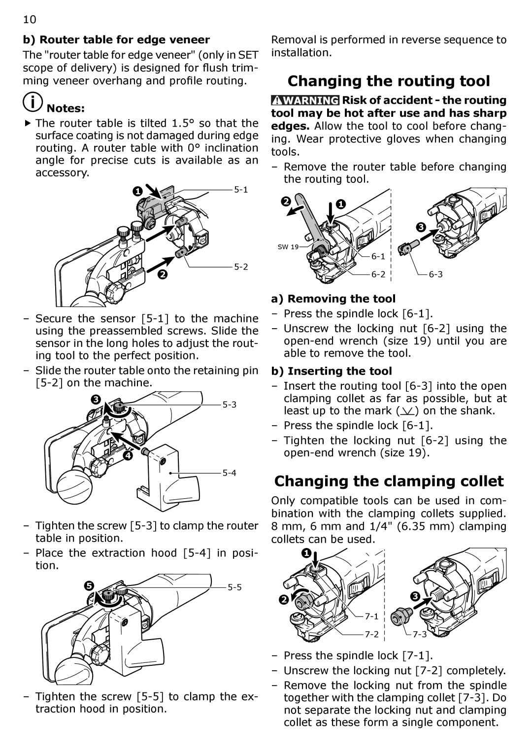
b) Router table for edge veneer
The "router table for edge veneer" (only in SET scope of delivery) is designed for flush trim- ming veneer overhang and profile routing.
![]() Notes:
Notes:
f The router table is tilted 1.5° so that the surface coating is not damaged during edge routing. A router table with 0° inclination angle for precise cuts is available as an accessory.
1 ![]() 5-1
5-1
Removal is performed in reverse sequence to installation.
Changing the routing tool
![]() Risk of accident - the routing tool may be hot after use and has sharp edges. Allow the tool to cool before chang-
Risk of accident - the routing tool may be hot after use and has sharp edges. Allow the tool to cool before chang-
ing. Wear protective gloves when changing tools.
–Remove the router table before changing the routing tool.
2 1
3
2
![]() 5-2
5-2
SW 19 |
a) Removing the tool
–Secure the sensor
–Slide the router table onto the retaining pin
3 | |
|
4
–Tighten the screw
–Place the extraction hood
5![]() 5-5
5-5
–Tighten the screw
–Press the spindle lock
–Unscrew the locking nut
b) Inserting the tool
–Insert the routing tool ![]() ) on the shank.
) on the shank.
–Press the spindle lock
–Tighten the locking nut
Changing the clamping collet
Only compatible tools can be used in com- bination with the clamping collets supplied. 8 mm, 6 mm and 1/4" (6.35 mm) clamping collets can be used.
1 |
|
2 | 3 |
| |
| |
–Press the spindle lock
–Unscrew the locking nut
–Remove the locking nut from the spindle together with the clamping collet