–Attach a different clamping collet with lock- ing nut to the spindle.
–Screw on the locking nut loosely. Do not tighten the locking nut until a router bit is inserted.
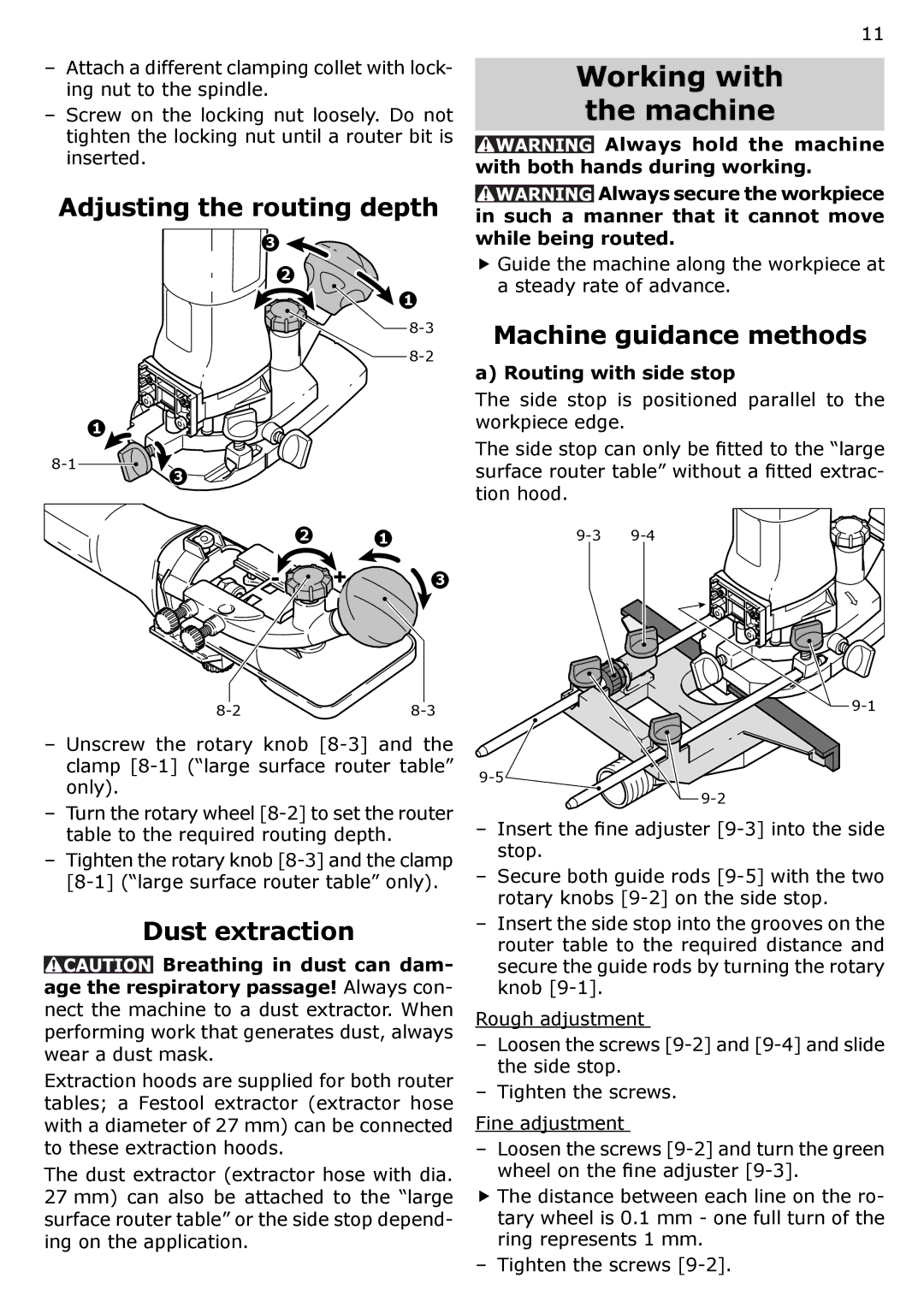
Adjusting the routing depth
3![]()
2
![]() 1
1
1
3
2 1
3
–Unscrew the rotary knob
–Turn the rotary wheel
–Tighten the rotary knob
Dust extraction
![]() Breathing in dust can dam- age the respiratory passage! Always con-
Breathing in dust can dam- age the respiratory passage! Always con-
nect the machine to a dust extractor. When performing work that generates dust, always wear a dust mask.
Extraction hoods are supplied for both router tables; a Festool extractor (extractor hose with a diameter of 27 mm) can be connected to these extraction hoods.
The dust extractor (extractor hose with dia. 27 mm) can also be attached to the “large surface router table” or the side stop depend- ing on the application.
11
Working with the machine
![]() Always hold the machine with both hands during working.
Always hold the machine with both hands during working.
![]() Always secure the workpiece in such a manner that it cannot move while being routed.
Always secure the workpiece in such a manner that it cannot move while being routed.
fGuide the machine along the workpiece at a steady rate of advance.
Machine guidance methods
a) Routing with side stop
The side stop is positioned parallel to the workpiece edge.
The side stop can only be fitted to the “large surface router table” without a fitted extrac- tion hood.
–Insert the fine adjuster
–Secure both guide rods
–Insert the side stop into the grooves on the router table to the required distance and secure the guide rods by turning the rotary knob
Rough adjustment
–Loosen the screws
–Tighten the screws.
Fine adjustment
–Loosen the screws
fThe distance between each line on the ro- tary wheel is 0.1 mm - one full turn of the ring represents 1 mm.
– Tighten the screws