Field Controls PVU-300 installation instructions Side Wall Vent Hood Installation

Models: PVU-300

1 16
Download 16 pages 61.77 Kb
Page 5
Image 5

SIDE WALL VENT HOOD INSTALLATION

1.Use the inside wall plate as a template to mark the hole location. Cut a hole 1 inch larger than the marked hole to facilitate easy installation (See Figure 4)

2.Center vent hood through the hole from outside. Fasten the vent hood to the outside wall with the appropriate type of mounting screws.

3.Fasten the wall end plate to the inside wall with the appropriate type of mounting screws. NOTE: Apply sealant to the outside mounting plate of the vent hood to prevent leakage.

4.Connect the venter outlet or a properly sized section of vent pipe onto the inner pipe of the vent hood. Fasten the connection with three sheet metal screws or equivalent fastening method.

5.Seal the vent hood inlet connection and any other vent pipe joints on the outlet side of the venter with an approved high temperature silicone adhesive sealant or equivalent material.

NOTE: Do not enclose the space between the plates on the outside of the vent hood or between the inner and outer pipe of the vent hood. This might

cause overheating of the wall structure. Local codes might require fencing around the vent hood outlet.

VENTER LOCATION

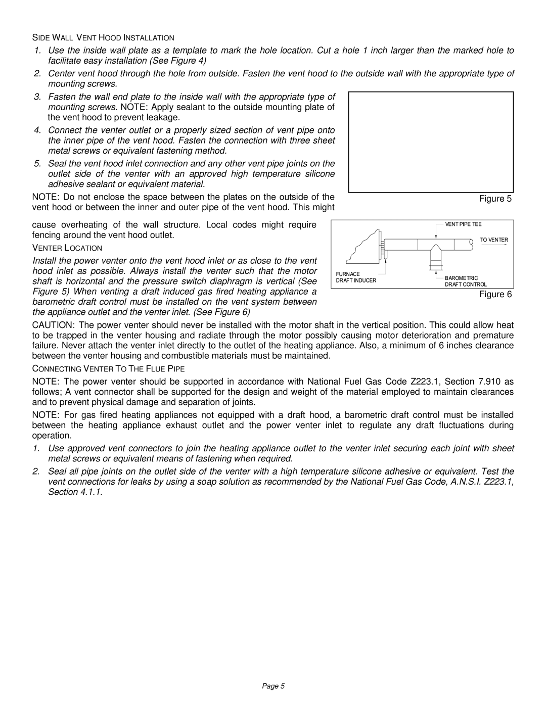
Install the power venter onto the vent hood inlet or as close to the vent hood inlet as possible. Always install the venter such that the motor shaft is horizontal and the pressure switch diaphragm is vertical (See Figure 5) When venting a draft induced gas fired heating appliance a barometric draft control must be installed on the vent system between the appliance outlet and the venter inlet. (See Figure 6)

Figure 5

Figure 6

CAUTION: The power venter should never be installed with the motor shaft in the vertical position. This could allow heat to be trapped in the venter housing and radiate through the motor possibly causing motor deterioration and premature failure. Never attach the venter inlet directly to the outlet of the heating appliance. Also, a minimum of 6 inches clearance between the venter housing and combustible materials must be maintained.

CONNECTING VENTER TO THE FLUE PIPE

NOTE: The power venter should be supported in accordance with National Fuel Gas Code Z223.1, Section 7.910 as follows; A vent connector shall be supported for the design and weight of the material employed to maintain clearances and to prevent physical damage and separation of joints.

NOTE: For gas fired heating appliances not equipped with a draft hood, a barometric draft control must be installed between the heating appliance exhaust outlet and the power venter inlet to regulate any draft fluctuations during operation.

1.Use approved vent connectors to join the heating appliance outlet to the venter inlet securing each joint with sheet metal screws or equivalent means of fastening when required.

2.Seal all pipe joints on the outlet side of the venter with a high temperature silicone adhesive or equivalent. Test the vent connections for leaks by using a soap solution as recommended by the National Fuel Gas Code, A.N.S.I. Z223.1, Section 4.1.1.

Page 5

Page 5
Image 5
Field Controls PVU-300 installation instructions Side Wall Vent Hood Installation

PVU-300 specifications

Field Controls PVU-300 is a highly esteemed device in the realm of indoor air quality management, particularly designed for residential and light commercial applications. This innovative product excels in providing a comprehensive solution for ventilating spaces while ensuring optimal comfort and air quality.

One of the main features of the PVU-300 is its capability to deliver fresh outdoor air efficiently into a building while exhausting stale indoor air. This is crucial for maintaining a healthy living or working environment. The unit comes equipped with multiple airflow configurations, allowing it to adapt seamlessly to various building sizes and layouts.

The PVU-300 utilizes advanced demand control ventilation technology, which adjusts ventilation rates based on the actual occupancy and indoor air quality needs. This not only enhances comfort but also improves energy efficiency, as the system reduces unnecessary energy consumption during periods of low occupancy.

Furthermore, the PVU-300 is designed with intuitive controls that allow for easy operation and monitoring. The user-friendly interface simplifies adjustments and settings, ensuring that users can easily manage their ventilation needs. This device is compatible with a range of sensors, enabling it to work in conjunction with CO2 and humidity controls, further optimizing performance.

In terms of construction, the PVU-300 is built with durability in mind. Its robust design ensures longevity and reliable operation in various environmental conditions. The unit also boasts a compact footprint, making it suitable for installation in tight spaces without compromising airflow performance.

The technology behind the PVU-300 includes high-efficiency fans that minimize noise levels while maximizing airflow. This ensures that the device operates quietly, providing a comfortable environment without distracting sounds.

Installation of the PVU-300 is straightforward, thanks to its flexible duct design and user-friendly mounting options. This efficiency not only saves time but also reduces labor costs associated with installation.

In conclusion, the Field Controls PVU-300 represents a significant advancement in ventilation technology, combining energy efficiency, user-friendliness, and adaptability to diverse environments. Its features and technological innovations make it an ideal choice for enhancing indoor air quality, ensuring spaces are both comfortable and healthy for occupants.