SYSTEM CONTROL CHECK PROCEDURES

1.Adjust the thermostat to call for heat and observe the power venting system for proper operation sequence. Repeat as necessary.

a.Thermostat calls for heat.

b.Venter relay is energized which starts venter motor.

c.Pressure switch closes which allows burner to fire.

d.Thermostat is satisfied, burner stops operation.

e.Venter continues to operate for up to 2 minutes during the post purge cycle.

2.While the system is in operation, disconnect the draft tube from the air pressure switch. The pressure switch should open and interrupt burner operation. Re-connect the draft tube to the air pressure switch, which should allow the burner re-light.

3.If a GSK-3 secondary safety switch is installed, allow the vent pipe to cool and disconnect the vent pipe between the appliance outlet and venter inlet. Block the vent connected to the appliance with a non-combustible material. Activate the heating system main burner and verify that the GSK-3 shuts down the burner within a few minutes or less. Reset the GSK-3 and repeat.

TROUBLESHOOTING TIPS

1.Burner does not fire when thermostat calls for heat.

a.Make sure draft tube is securely fastened to the air pressure switch, and is not blocked.

b.Check for continuity across pressure switch terminals when venter is operating.

c.Check wiring connections between air pressure switch, appliance, relay, yellow mode wire connection and PVU control board.

d.Relay should “click” when pressure switch closes.

2.Venter does not activate when thermostat calls for heat.

a.Check to see if relay closes when thermostat calls for heat.

b.Check wiring connections, including yellow mode wire connection.

c.Check motor for unrestricted shaft rotation.

3.Exhaust gas odor.

a.Check system draft level during operation.

b.Check vent system on outlet side of venter for leakage.

c.Check for negative pressure in building.

MAINTENANCE

1.Motor: Inspect the motor once a year - motor should rotate freely. The PVU’s motor has sealed ball bearings, therefore, should not need oiling.

2.Blower Wheel: Inspect the blower wheel annually to clear any soot, ash or coating, which inhibits either rotation or airflow. Remove all foreign materials before operating.

3.Vent System: Inspect all vent connections annually for looseness, for evidence of corrosion and for flue gas leakage. Replace, seal, or tighten pipe connections if necessary. Check the power venter choke plate to insure it is secured in place. Check the barometric draft control, if installed, to insure the gate swings freely.

4.System Safety Devices: With the heating system operating disconnect the pressure sensing tube from the pressure switch on the venter. This should stop the burner operation. Re-connecting the tube will relight the burner. For 30 millivolt operating systems, disconnect one lead of the spill switch circuit from the thermocouple junction block. This should shut off the pilot and the burner. Re-connection will allow re-lighting of the pilot.

REPLACEMENT PARTS LIST

The following items are available for replacement, if necessary.

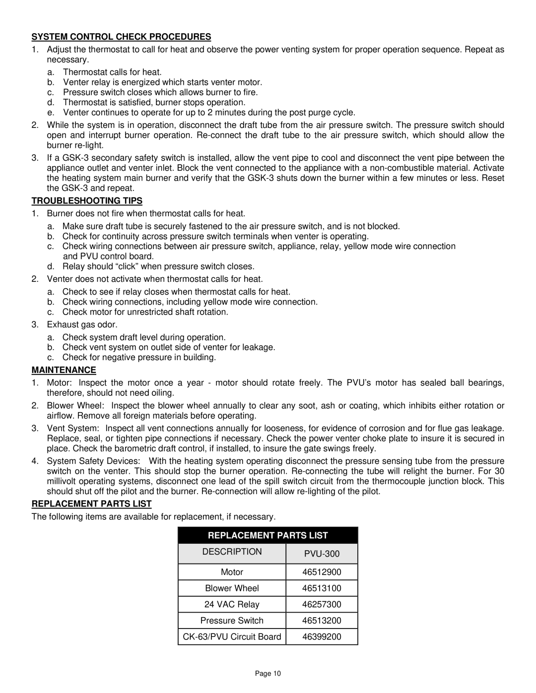
REPLACEMENT PARTS LIST

DESCRIPTION

PVU-300


Motor

46512900


Blower Wheel

46513100


24 VAC Relay

46257300


Pressure Switch

46513200


CK-63/PVU Circuit Board

46399200


Page 10

Page 10
Image 10
Field Controls PVU-300 System Control Check Procedures, Troubleshooting Tips, Maintenance, Replacement Parts List

PVU-300 specifications

Field Controls PVU-300 is a highly esteemed device in the realm of indoor air quality management, particularly designed for residential and light commercial applications. This innovative product excels in providing a comprehensive solution for ventilating spaces while ensuring optimal comfort and air quality.

One of the main features of the PVU-300 is its capability to deliver fresh outdoor air efficiently into a building while exhausting stale indoor air. This is crucial for maintaining a healthy living or working environment. The unit comes equipped with multiple airflow configurations, allowing it to adapt seamlessly to various building sizes and layouts.

The PVU-300 utilizes advanced demand control ventilation technology, which adjusts ventilation rates based on the actual occupancy and indoor air quality needs. This not only enhances comfort but also improves energy efficiency, as the system reduces unnecessary energy consumption during periods of low occupancy.

Furthermore, the PVU-300 is designed with intuitive controls that allow for easy operation and monitoring. The user-friendly interface simplifies adjustments and settings, ensuring that users can easily manage their ventilation needs. This device is compatible with a range of sensors, enabling it to work in conjunction with CO2 and humidity controls, further optimizing performance.

In terms of construction, the PVU-300 is built with durability in mind. Its robust design ensures longevity and reliable operation in various environmental conditions. The unit also boasts a compact footprint, making it suitable for installation in tight spaces without compromising airflow performance.

The technology behind the PVU-300 includes high-efficiency fans that minimize noise levels while maximizing airflow. This ensures that the device operates quietly, providing a comfortable environment without distracting sounds.

Installation of the PVU-300 is straightforward, thanks to its flexible duct design and user-friendly mounting options. This efficiency not only saves time but also reduces labor costs associated with installation.

In conclusion, the Field Controls PVU-300 represents a significant advancement in ventilation technology, combining energy efficiency, user-friendliness, and adaptability to diverse environments. Its features and technological innovations make it an ideal choice for enhancing indoor air quality, ensuring spaces are both comfortable and healthy for occupants.