Page 5 of 14 |
3.Hardware Connections
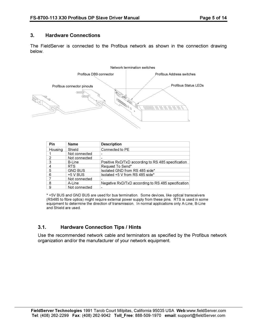
The FieldServer is connected to the Profibus network as shown in the connection drawing below.
Network termination switches |
|
Profibus DB9 connector | Profibus Address switches |
Profibus connector pinouts
Profibus Status LEDs
Pin | Name | Description |
|
|
|
Housing | Shield | Connected to PE |
1 | Not connected | - |
2 | Not connected | - |
3 | Positive RxD/TxD according to RS 485 specification | |
4 | RTS | Request To Send* |
5 | GND BUS | Isolated GND from RS 485 side* |
6 | +5 V BUS | Isolated +5 V from RS 485 side* |
7 | Not connected | - |
8 | Negative RxD/TxD according to RS 485 specification | |
9 | Not connected | - |
*+5V BUS and GND BUS are used for bus termination. Some devices, like optical transceivers (RS485 to fibre optics) might require external power supply from these pins. RTS is used in some equipment to determine the direction of transmission. In normal applications only
3.1.Hardware Connection Tips / Hints
Use the recommended network cable and terminators as specified by the Profibus network organization and/or the manufacturer of your network equipment.
FieldServer Technologies 1991 Tarob Court Milpitas, California 95035 USA Web:www.fieldServer.com Tel: (408)
