INSTALLATION, Continued
BEFORE YOU BEGIN INSTALLATION
This unit is designed to be mounted on any standard wiring junction box up to a
•Make sure the alarm is not receiving excessively noisy power. Examples of noisy power could be major appliances on the same circuit, power from a generator or solar power, light dim- mer on the same circuit or mounted near fluorescent lighting. Excessively noisy power may cause damage to your Alarm.
Find the pair of
•On each label write in the phone number of your emergency responder (like 911) and a qualified appliance technician.
•Place one label near the Smoke/CO Alarm, and the other label in the “fresh air” location you plan to go if the alarm sounds.
NOTE: A qualified appliance technician is defined as “a person, firm, corporation, or company that either in person or through a representa- tive, is engaged in and responsible for the installation, testing, servicing, or replacement of heating, ventilation, air conditioning (HVAC) equipment, combustion appliances and equipment, and/or gas fireplaces or other decorative combustion equipment.”
STAND ALONE ALARM ONLY:
•Connect the white wire on the power connector to the neutral wire in the junction box.
•Connect the black wire on the power connector to the hot wire in the junction box.
•Tuck the orange wire inside the junction box. It is used for interconnect only.
INTERCONNECTED ALARMS ONLY:
Strip off about 1/2” of the plastic coating on the orange interconnect wire on the power connector.
• Connect the white wire on the power connector to the neutral |
wire (usually white) in the junction box. |
• Connect the black wire on the power connector to the hot wire |
(usually black) in the junction box. |
• Connect the orange wire on the power connector to the inter- |
connect wire in the junction box. Repeat for each unit you are |
interconnecting. Never connect the hot or neutral wires in the |
junction box to the orange interconnect wire. Never cross hot |
and neutral wires between interconnected Alarms. |
3. Plug the power connector into the back of the Smoke/CO Alarm. |
4. Position the base of the Smoke/CO Alarm over the mounting bracket |
and turn. The Alarm will remain secure over a wide rotation range to |
allow for perfect alignment. When wall mounting, this will allow fine- |
tuning on the positioning to compensate for out of aligned wall studs |
1
2
3 ![]()
74
8
3
2 |
6
![]() 5
5
9
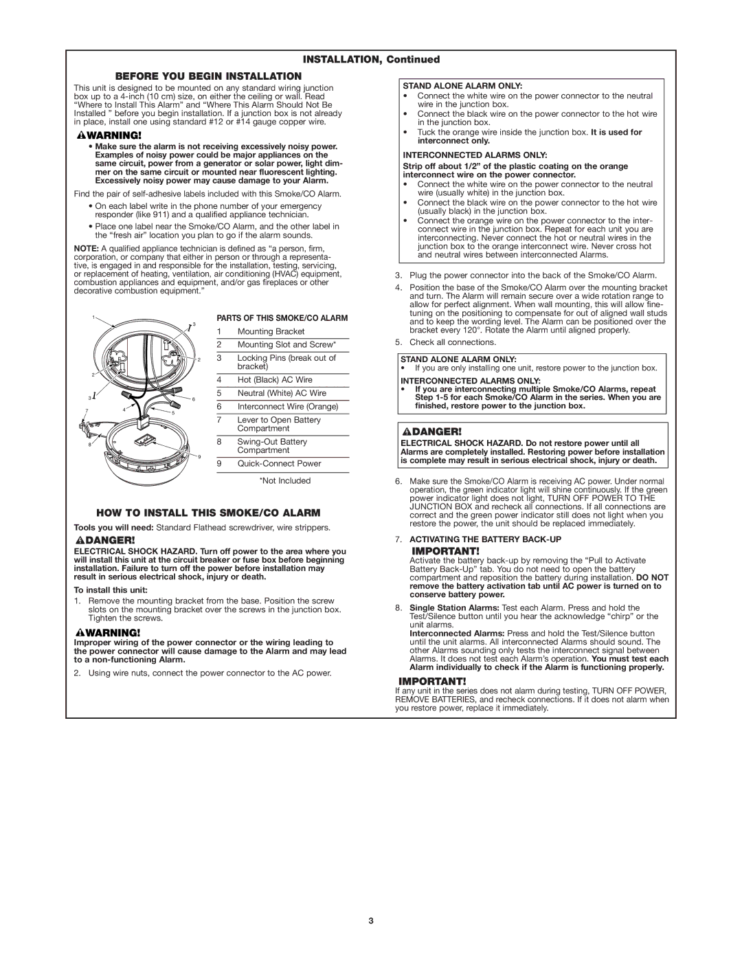
PARTS OF THIS SMOKE/CO ALARM
1Mounting Bracket
2Mounting Slot and Screw*
3Locking Pins (break out of bracket)
4Hot (Black) AC Wire
5Neutral (White) AC Wire
6Interconnect Wire (Orange)
7Lever to Open Battery Compartment
8
9
*Not Included
and to keep the wording level. The Alarm can be positioned over the |
bracket every 120°. Rotate the Alarm until aligned properly. |
5. Check all connections. |
STAND ALONE ALARM ONLY:
•If you are only installing one unit, restore power to the junction box.
INTERCONNECTED ALARMS ONLY:
•If you are interconnecting multiple Smoke/CO Alarms, repeat Step
ELECTRICAL SHOCK HAZARD. Do not restore power until all Alarms are completely installed. Restoring power before installation is complete may result in serious electrical shock, injury or death.
6. Make sure the Smoke/CO Alarm is receiving AC power. Under normal |
operation, the green indicator light will shine continuously. If the green |
power indicator light does not light, TURN OFF POWER TO THE |
JUNCTION BOX and recheck all connections. If all connections are |
HOW TO INSTALL THIS SMOKE/CO ALARM
Tools you will need: Standard Flathead screwdriver, wire strippers.
ELECTRICAL SHOCK HAZARD. Turn off power to the area where you will install this unit at the circuit breaker or fuse box before beginning installation. Failure to turn off the power before installation may result in serious electrical shock, injury or death.
To install this unit:
1.Remove the mounting bracket from the base. Position the screw slots on the mounting bracket over the screws in the junction box. Tighten the screws.
Improper wiring of the power connector or the wiring leading to the power connector will cause damage to the Alarm and may lead to a
2. Using wire nuts, connect the power connector to the AC power.
correct and the green power indicator still does not light when you |
restore the power, the unit should be replaced immediately. |
7. ACTIVATING THE BATTERY |
Activate the battery |
Battery |
compartment and reposition the battery during installation. DO NOT |
remove the battery activation tab until AC power is turned on to |
conserve battery power. |
8. Single Station Alarms: Test each Alarm. Press and hold the |
Test/Silence button until you hear the acknowledge “chirp” or the |
unit alarms. |
Interconnected Alarms: Press and hold the Test/Silence button |
until the unit alarms. All interconnected Alarms should sound. The |
other Alarms sounding only tests the interconnect signal between |
Alarms. It does not test each Alarm’s operation. You must test each |
Alarm individually to check if the Alarm is functioning properly. |
If any unit in the series does not alarm during testing, TURN OFF POWER, REMOVE BATTERIES, and recheck connections. If it does not alarm when you restore power, replace it immediately.
3
