System Installation | Connector |
2.4Connector Pin-outs
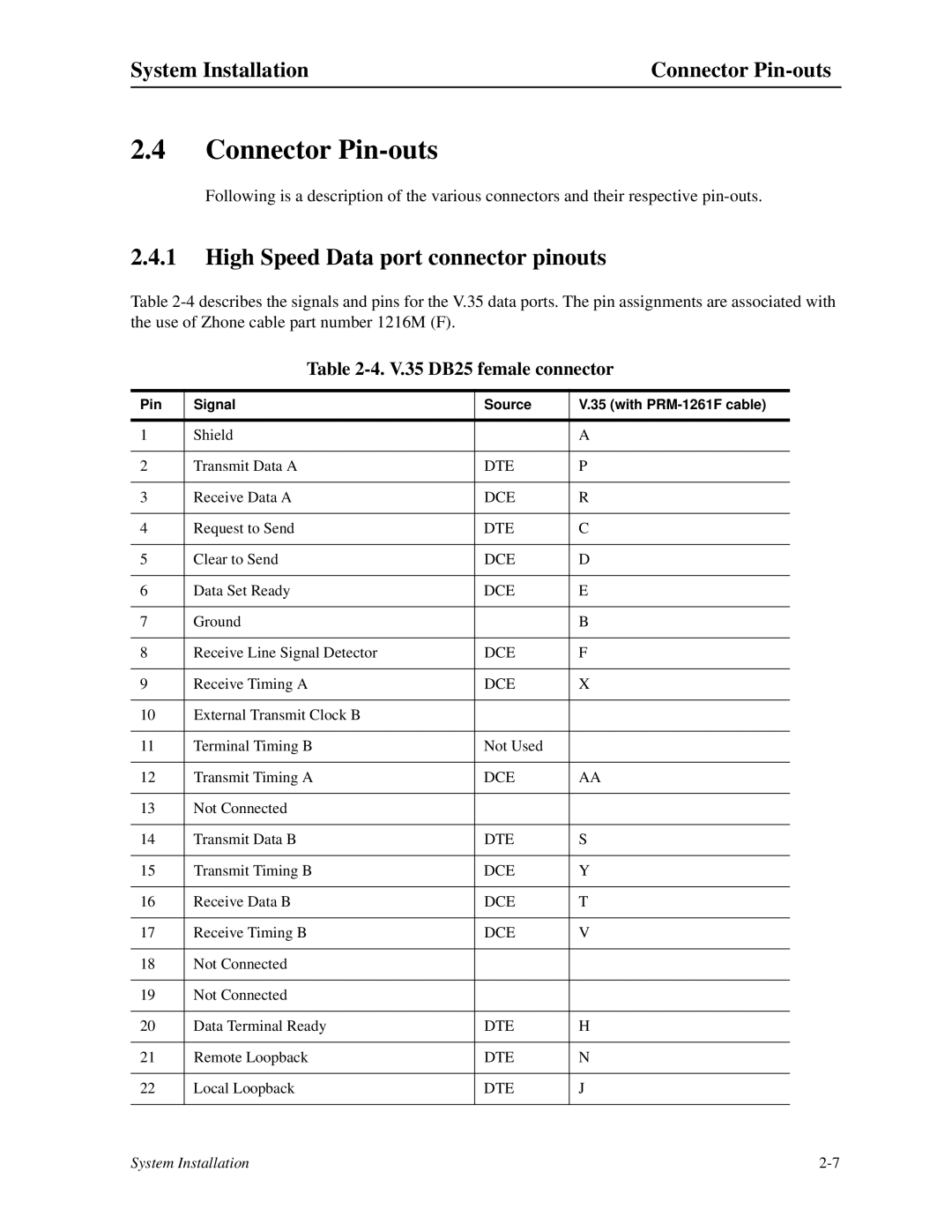
Following is a description of the various connectors and their respective
2.4.1High Speed Data port connector pinouts
Table
Table 2-4. V.35 DB25 female connector
Pin | Signal | Source | V.35 (with |
|
|
|
|
1 | Shield |
| A |
|
|
|
|
2 | Transmit Data A | DTE | P |
|
|
|
|
3 | Receive Data A | DCE | R |
|
|
|
|
4 | Request to Send | DTE | C |
|
|
|
|
5 | Clear to Send | DCE | D |
|
|
|
|
6 | Data Set Ready | DCE | E |
|
|
|
|
7 | Ground |
| B |
|
|
|
|
8 | Receive Line Signal Detector | DCE | F |
|
|
|
|
9 | Receive Timing A | DCE | X |
|
|
|
|
10 | External Transmit Clock B |
|
|
|
|
|
|
11 | Terminal Timing B | Not Used |
|
|
|
|
|
12 | Transmit Timing A | DCE | AA |
|
|
|
|
13 | Not Connected |
|
|
|
|
|
|
14 | Transmit Data B | DTE | S |
|
|
|
|
15 | Transmit Timing B | DCE | Y |
|
|
|
|
16 | Receive Data B | DCE | T |
|
|
|
|
17 | Receive Timing B | DCE | V |
|
|
|
|
18 | Not Connected |
|
|
|
|
|
|
19 | Not Connected |
|
|
|
|
|
|
20 | Data Terminal Ready | DTE | H |
|
|
|
|
21 | Remote Loopback | DTE | N |
|
|
|
|
22 | Local Loopback | DTE | J |
|
|
|
|
System Installation |