PATTRN
The Pattern is the outgoing test pattern to be sent to the selected port by the system. You can send a different pattern to each port. The none setting disables the test pattern. The
SIG CONV
The Signaling Conversion parameter allows you to change the transmit ABCD signaling bits from CCITT (E1) to ANSI (T1) standards, and is accessd by selecting B from the taBs option at the bottom of the window.
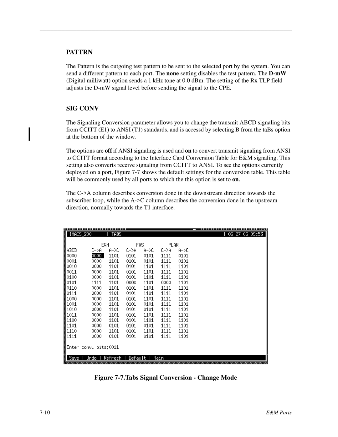
The options are off if ANSI signaling is used and on to convert transmit signaling from ANSI to CCITT format according to the Interface Card Conversion Table for E&M signaling. This setting also converts receive signaling from CCITT to ANSI. To see the options currently deployed on a port, Figure
The
Figure 7-7.Tabs Signal Conversion - Change Mode
E&M Ports |