A.4.3 E&M port Specifications
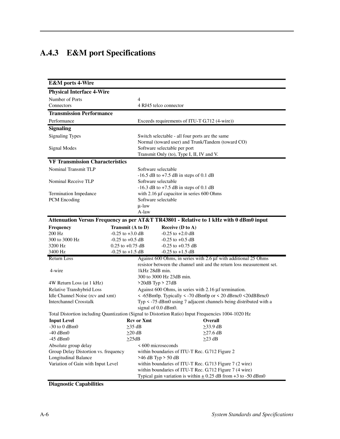
E&M ports
Physical Interface
Number of Ports | 4 |
Connectors | 4 RJ45 telco connector |
Transmission Performance
Performance | Exceeds requirements of |
Signaling |
|
Signaling Types | Switch selectable - all four ports are the same |
| Normal (toward user) and Trunk/Tandem (toward CO) |
Signal Modes | Software selectable per port |
| Transmit Only (to), Type I, II, IV and V. |
|
|
VF Transmission Characteristics |
|
Nominal Transmit TLP | Software selectable |
| |
Nominal Receive TLP | Software selectable |
| |
Termination Impedance | with 2.16 ∝ f capacitor in series 600 Ohms |
PCM Encoding | Software selectable |
| ∝ |
|
Attenuation Versus Frequency as per AT&T TR43801 - Relative to 1 kHz with 0 dBm0 input
Frequency | Transmit (A to D) | Receive (D to A) |
200 Hz | ||
300 to 3000 Hz | ||
3200 Hz | 0.25 to +0.75 dB | |
3400 Hz | ||
|
|
|
Return Loss | Against 600 Ohms, in series with 2.6 ∝ f with additional 25 Ohms |
| resistor between the channel unit and the return loss measurement set. |
1kHz 28dB min. | |
| 300 to 3000 Hz 23dB min. |
4W Return Loss (at 1 kHz) | >20dB Typ > 27dB |
Relative Transhybrid Loss | Against 600 Ohms, in series with 2.16 ∝ f termination. |
Idle Channel Noise (rcv and xmt) | < |
Interchannel Crosstalk | Typ < |
| signal of 0.0 dBm0. |
Total Distortion including Quantization (Signal to Distortion Ratio) Input Frequencies
Input Level
Group Delay Distortion vs. frequency Longitudinal Balance
Variation of Gain with Input Level
Rcv or Xmt | Overall |
>35 dB | >33.9 dB |
>20 dB | >27.6 dB |
>25dB | >23 dB |
< 600 microseconds
within boundaries of
within boundaries of
Diagnostic Capabilities
System Standards and Specifications |