Connector | System Installation |
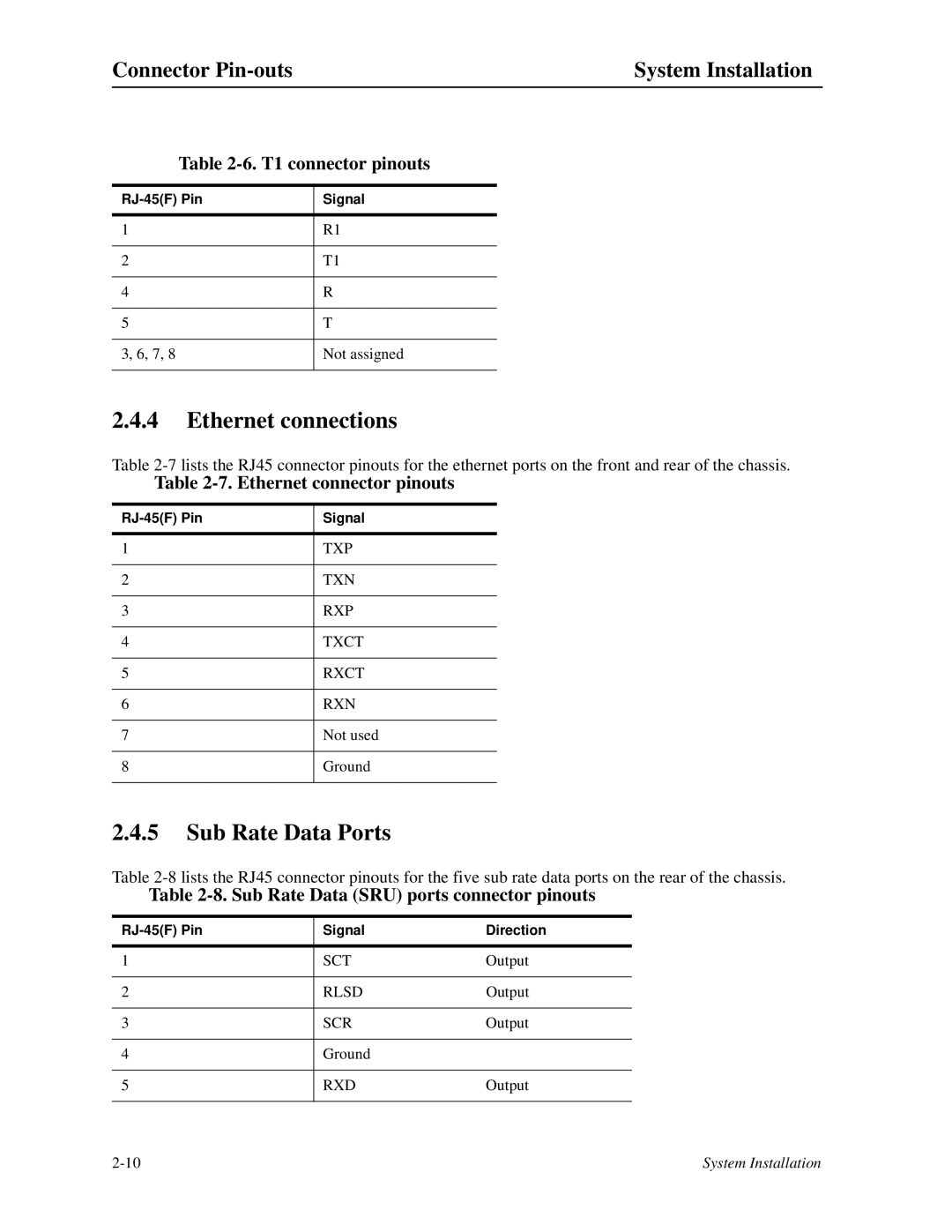
Table 2-6. T1 connector pinouts
Signal | |
|
|
1 | R1 |
|
|
2 | T1 |
|
|
4 | R |
|
|
5 | T |
|
|
3, 6, 7, 8 | Not assigned |
|
|
2.4.4Ethernet connections
Table
Table 2-7. Ethernet connector pinouts
Signal | |
|
|
1 | TXP |
|
|
2 | TXN |
|
|
3 | RXP |
|
|
4 | TXCT |
|
|
5 | RXCT |
|
|
6 | RXN |
|
|
7 | Not used |
|
|
8 | Ground |
|
|
2.4.5Sub Rate Data Ports
Table
Table 2-8. Sub Rate Data (SRU) ports connector pinouts
Signal | Direction | |
|
|
|
1 | SCT | Output |
|
|
|
2 | RLSD | Output |
|
|
|
3 | SCR | Output |
|
|
|
4 | Ground |
|
|
|
|
5 | RXD | Output |
|
|
|
System Installation |