Power and Grounding on the | System Installation |
2.5.8AC power installation
If ordered as an AC unit, the
2.5.9Powering Up the System
After connecting the chassis to the external power sources and making the proper ground connections, apply power to the chassis. Plug the AC power cord into the associated electrical outlets, or turn on the external DC power supply. Then, observe the following
1.On
Orange, Green, Red and blank.
2.The POWER LED then will turn green on the chassis faceplate. The ACTIVE LED will stay orange until the unit boot cycle is completed, and then turn green.
If no LEDs illuminate, verify that the external power source is providing power to the chassis, and check the connection between that source and the chassis.
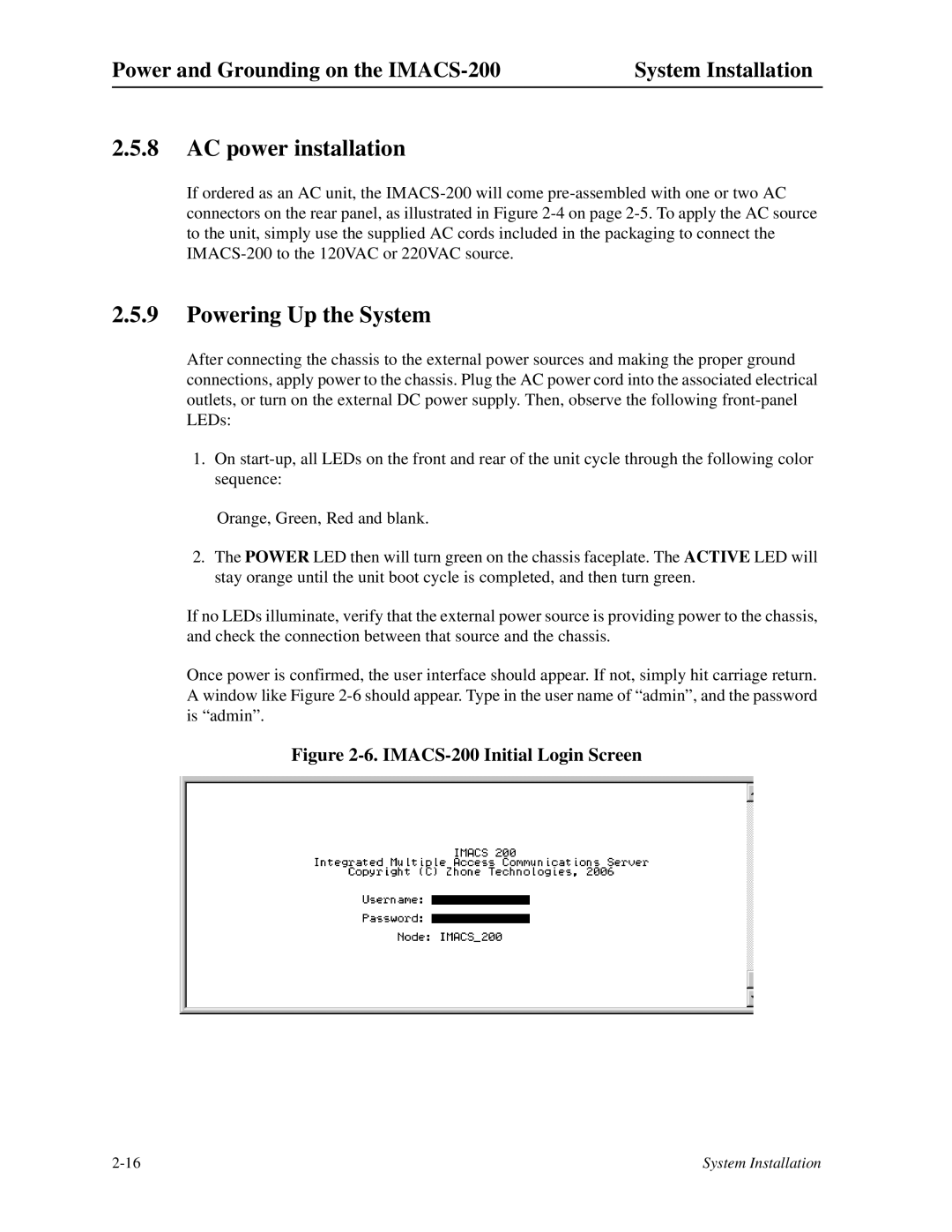
Once power is confirmed, the user interface should appear. If not, simply hit carriage return. A window like Figure
Figure 2-6. IMACS-200 Initial Login Screen
System Installation |