Connector Types | System Installation |
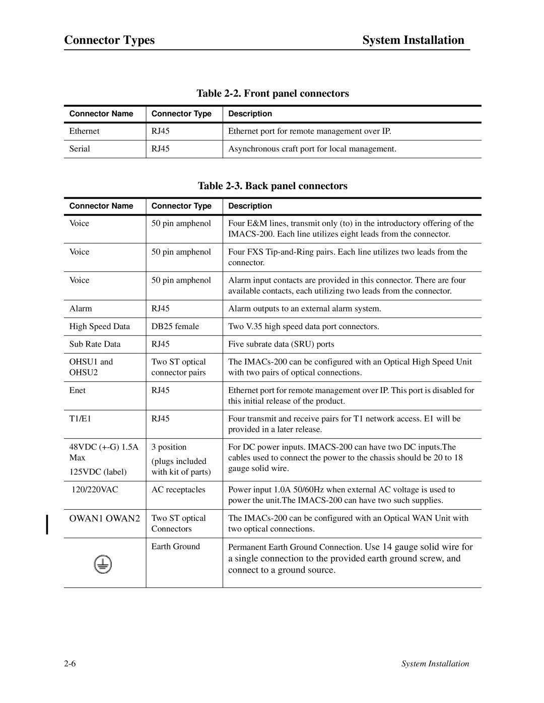
Table 2-2. Front panel connectors
Connector Name | Connector Type | Description |
|
|
|
Ethernet | RJ45 | Ethernet port for remote management over IP. |
|
|
|
Serial | RJ45 | Asynchronous craft port for local management. |
|
|
|
Table 2-3. Back panel connectors
Connector Name | Connector Type | Description | |
|
|
| |
Voice | 50 pin amphenol | Four E&M lines, transmit only (to) in the introductory offering of the | |
|
| ||
|
|
| |
Voice | 50 pin amphenol | Four FXS | |
|
| connector. | |
|
|
| |
Voice | 50 pin amphenol | Alarm input contacts are provided in this connector. There are four | |
|
| available contacts, each utilizing two leads from the connector. | |
|
|
| |
Alarm | RJ45 | Alarm outputs to an external alarm system. | |
|
|
| |
High Speed Data | DB25 female | Two V.35 high speed data port connectors. | |
|
|
| |
Sub Rate Data | RJ45 | Five subrate data (SRU) ports | |
|
|
| |
OHSU1 and | Two ST optical | The | |
OHSU2 | connector pairs | with two pairs of optical connections. | |
|
|
| |
Enet | RJ45 | Ethernet port for remote management over IP. This port is disabled for | |
|
| this initial release of the product. | |
|
|
| |
T1/E1 | RJ45 | Four transmit and receive pairs for T1 network access. E1 will be | |
|
| provided in a later release. | |
|
|
| |
48VDC | 3 position | For DC power inputs. | |
Max | (plugs included | cables used to connect the power to the chassis should be 20 to 18 | |
| gauge solid wire. | ||
125VDC (label) | with kit of parts) | ||
| |||
|
|
| |
120/220VAC | AC receptacles | Power input 1.0A 50/60Hz when external AC voltage is used to | |
|
| power the unit.The | |
|
|
| |
OWAN1 OWAN2 | Two ST optical | The | |
| Connectors | two optical connections. | |
|
|
| |
| Earth Ground | Permanent Earth Ground Connection. Use 14 gauge solid wire for | |
|
| a single connection to the provided earth ground screw, and | |
|
| connect to a ground source. | |
|
|
|
System Installation |
