System Installation 2-5

System Installation Connector Types

Figure 2-3.Chassis Mounting Holes
Table 2-1 outlines the minimum clearance that is re commended for the IMACS-200 on all fou r
sides.
Table 2-1. Minimum Chassis Clearances
2.3 Connector Types
The product is equipped with several types of electrical connections to the network and power
sources. Table 2-2 lists the connections on the front panel of the IMACS-200 (Ref er to Figure
2-1 on page 2-4 for an illustration of the IMACS-200 front panel). These connections are
available for the crafts person to gain easy access into the unit. T abl e 2- 3 lis ts the ba ck panel
connectors along with their functionality. (Refer to Figure 2-4 on page 2-5 for an illustration
of the IMACS-200 back panel)
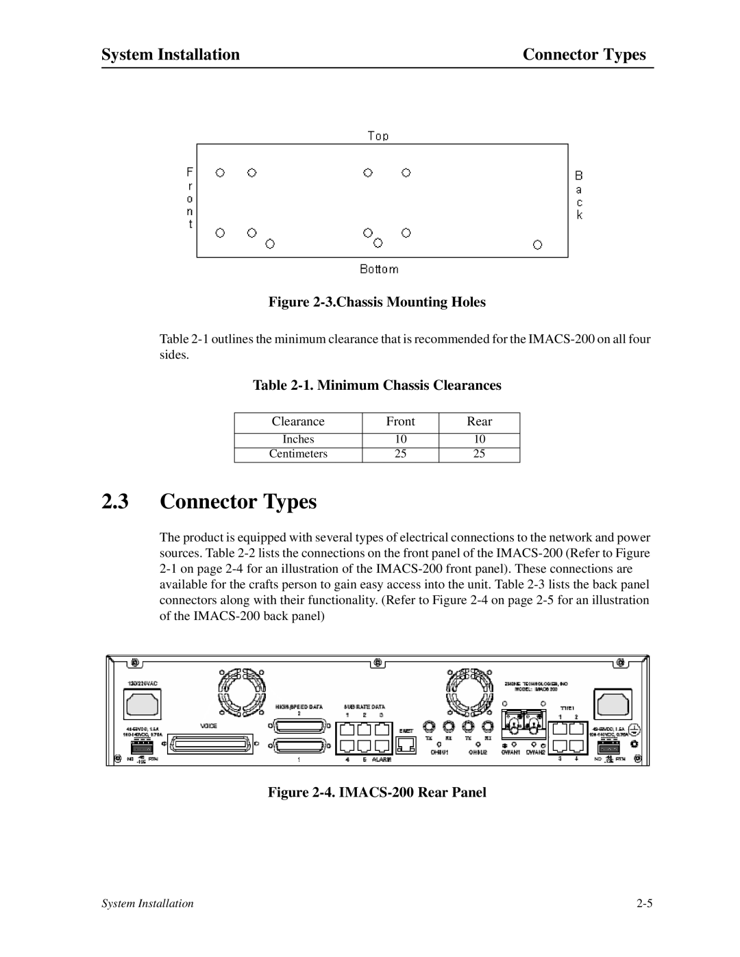
Figure 2-4. IMACS-200 Rear Panel
Clearance Front Rear
Inches 10 10
Centimeters 25 25