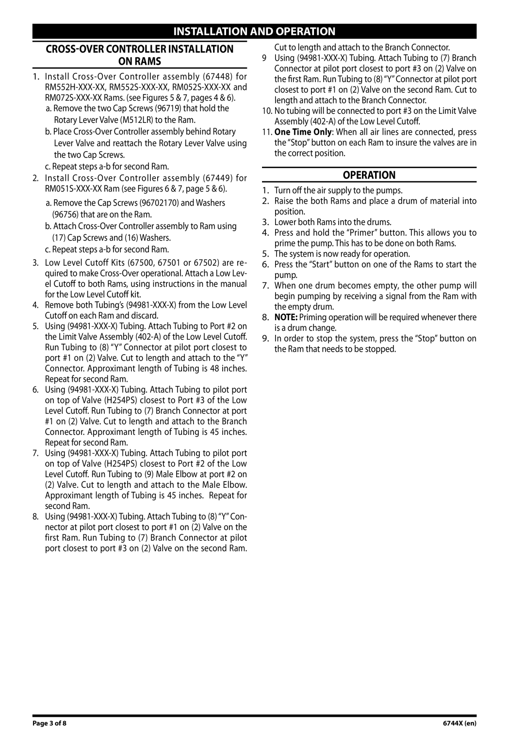
6744X specifications
Ingersoll-Rand 6744X is a highly regarded model in the realm of air compressors, showcasing a blend of advanced engineering and user-centric design. This specific model is ideally suited for various applications, ranging from industrial use to more specialized requirements in the construction and automotive sectors. Its robust construction and high performance make it a staple for professionals who demand reliability and efficiency in their tools.One of the hallmark features of the Ingersoll-Rand 6744X is its exceptional air output capability, which allows it to deliver a consistent flow of compressed air. This is crucial for powering pneumatic tools, running machinery, and other applications where air pressure is essential. Notably, the compressor offers a high pressure-to-volume ratio, ensuring that users benefit from both quantity and quality in their air supply.
The 6744X utilizes state-of-the-art technology, such as a patented airend design that maximizes efficiency while minimizing energy consumption. This not only reduces operational costs but also makes the compressor more environmentally friendly. Furthermore, the integrated variable speed drive technology adapts to fluctuating demand, ensuring that energy is used wisely, without sacrificing performance.
Durability is another defining characteristic of the Ingersoll-Rand 6744X. With rugged construction materials and a reinforced build, it is designed to withstand the rigors of heavy-duty use. Additionally, many components are easily accessible, enabling quick maintenance and reducing downtime. This combination of durability and ease of maintenance ensures that operators can rely on this compressor for extensive periods without significant performance degradation.
Moreover, the model is equipped with intelligent control systems that offer real-time monitoring of the compressor’s performance metrics. This feature allows users to optimize settings for different applications, ensuring maximum output and efficiency. The intuitive interface provides alerts and diagnostics, further enhancing operational effectiveness.
In conclusion, the Ingersoll-Rand 6744X stands out in the competitive market of air compressors due to its remarkable features, efficient technologies, and robust characteristics. Whether you're in need of reliable air supply for powering tools or industrial machinery, the 6744X delivers on all fronts, making it a worthy investment for professionals across multiple industries.

