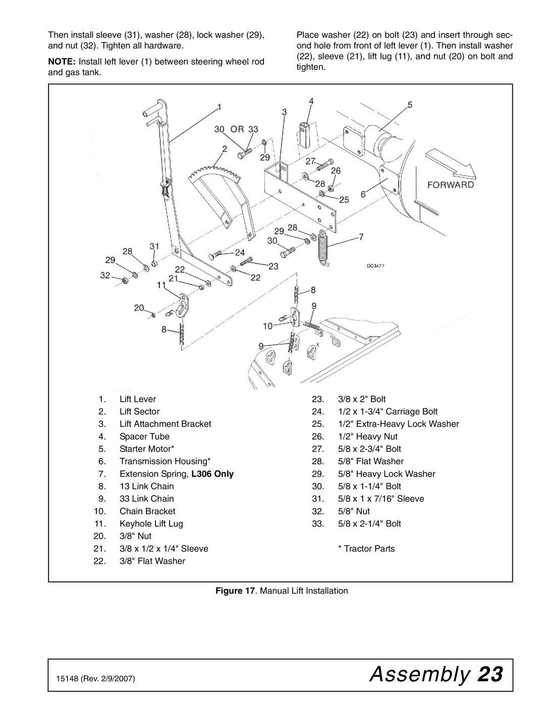
Then install sleeve (31), washer (28), lock washer (29), and nut (32). Tighten all hardware.
NOTE: Install left lever (1) between steering wheel rod and gas tank.
Place washer (22) on bolt (23) and insert through sec- ond hole from front of left lever (1). Then install washer (22), sleeve (21), lift lug (11), and nut (20) on bolt and tighten.
1. | Lift Lever | 23. | 3/8 x 2" Bolt |
2. | Lift Sector | 24. | 1/2 x |
3. | Lift Attachment Bracket | 25. | 1/2" |
4. | Spacer Tube | 26. | 1/2" Heavy Nut |
5. | Starter Motor* | 27. | 5/8 x |
6. | Transmission Housing* | 28. | 5/8" Flat Washer |
7. | Extension Spring, L306 Only | 29. | 5/8" Heavy Lock Washer |
8. | 13 Link Chain | 30. | 5/8 x |
9. | 33 Link Chain | 31. | 5/8 x 1 x 7/16" Sleeve |
10. | Chain Bracket | 32. | 5/8" Nut |
11. | Keyhole Lift Lug | 33. | 5/8 x |
20.3/8" Nut
21. | 3/8 x 1/2 x 1/4" Sleeve | * Tractor Parts |
22. | 3/8" Flat Washer |
|
Figure 17. Manual Lift Installation
15148 (Rev. 2/9/2007) | Assembly 23 |
|
|