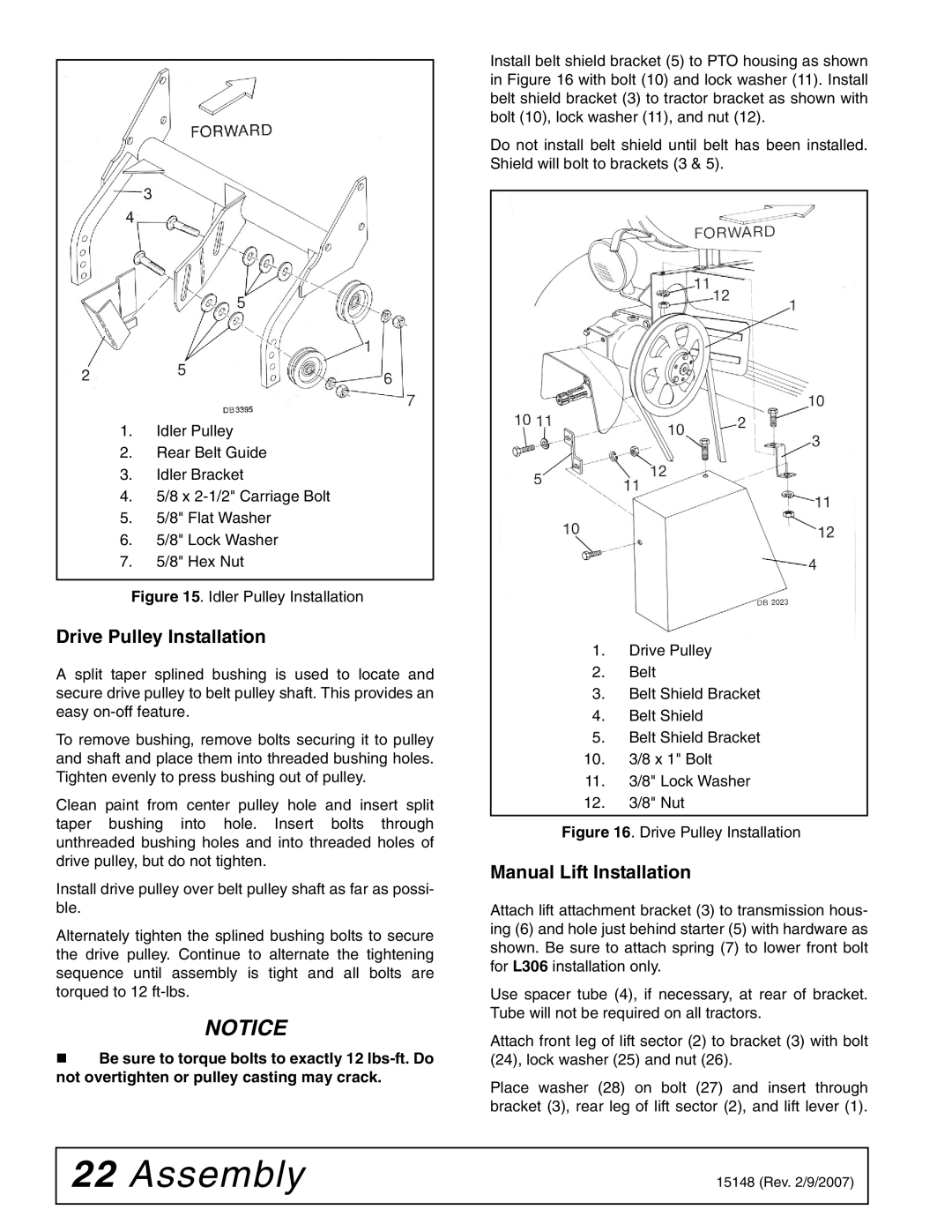
1.Idler Pulley
2.Rear Belt Guide
3.Idler Bracket
4.5/8 x
5.5/8" Flat Washer
6.5/8" Lock Washer
7.5/8" Hex Nut
Figure 15. Idler Pulley Installation
Drive Pulley Installation
A split taper splined bushing is used to locate and secure drive pulley to belt pulley shaft. This provides an easy
To remove bushing, remove bolts securing it to pulley and shaft and place them into threaded bushing holes. Tighten evenly to press bushing out of pulley.
Clean paint from center pulley hole and insert split taper bushing into hole. Insert bolts through unthreaded bushing holes and into threaded holes of drive pulley, but do not tighten.
Install drive pulley over belt pulley shaft as far as possi- ble.
Alternately tighten the splined bushing bolts to secure the drive pulley. Continue to alternate the tightening sequence until assembly is tight and all bolts are torqued to 12
NOTICE
Be sure to torque bolts to exactly 12
Install belt shield bracket (5) to PTO housing as shown in Figure 16 with bolt (10) and lock washer (11). Install belt shield bracket (3) to tractor bracket as shown with bolt (10), lock washer (11), and nut (12).
Do not install belt shield until belt has been installed. Shield will bolt to brackets (3 & 5).
1.Drive Pulley
2.Belt
3.Belt Shield Bracket
4.Belt Shield
5.Belt Shield Bracket
10.3/8 x 1" Bolt
11.3/8" Lock Washer
12.3/8" Nut
Figure 16. Drive Pulley Installation
Manual Lift Installation
Attach lift attachment bracket (3) to transmission hous- ing (6) and hole just behind starter (5) with hardware as shown. Be sure to attach spring (7) to lower front bolt for L306 installation only.
Use spacer tube (4), if necessary, at rear of bracket. Tube will not be required on all tractors.
Attach front leg of lift sector (2) to bracket (3) with bolt (24), lock washer (25) and nut (26).
Place washer (28) on bolt (27) and insert through bracket (3), rear leg of lift sector (2), and lift lever (1).
22 Assembly | 15148 (Rev. 2/9/2007) |
|
|