Manuals
/
Woods Equipment
/
Lawn and Garden
/
Lawn Mower
Woods Equipment
L59A-3, L306A-3
manual
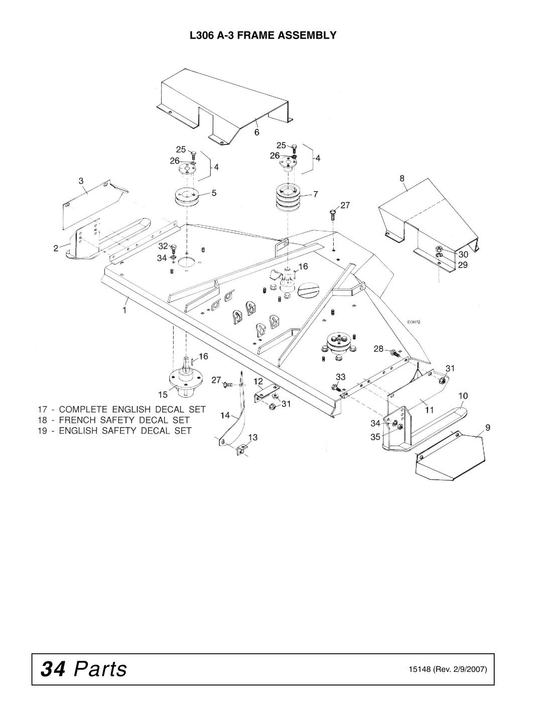
L306 A-3 Frame Assembly
Models:
L306A-3
L59A-3
1
34
50
50
Download
50 pages
8.41 Kb
31
32
33
34
35
36
37
38
Troubleshooting
Specs
Install
Bolt Torque Chart
Warranty
Maintenance
Assembly
Adjustments
Cleaning
Safety
Page 34
Image 34
L306
A-3
FRAME ASSEMBLY
34
Parts
15148 (Rev. 2/9/2007)
Page 33
Page 35
Page 34
Image 34
Page 33
Page 35
Contents
Rotary Mower
Introduction
To the Dealer
Table of Contents
LEA EL Instructivo
General Information
Specifications
L59A-3 L306A-3
Training
Safety
Safety Rules
Preparation
Transportation
Maintenance
Storage
Safety & Instructional Decals
Serial Number Plate
Operation
Adjustments
Cutting Height Adjustment
Operation
Starting and Stopping Mower
Side Skid Adjustment
Mower Attitude
PRE-OPERATION Check List
Mowing Techniques
Transporting
Commencing Mowing
Mowing Speed
Uneven Terrain
Lubrication
Owner Service
Owner Service
Blade Servicing
Sharpening
Removal and Installation
L59 Installation
L59 Removal
Belt Replacement
Cleaning
L306 Installation
After Each Use
Dealer Service
Dealer Service
Blade Spindle Repair
Installation
Left Hand Threads
Troubleshooting
Troubleshooting Mowing Conditions
Troubleshooting Belt Conditions
Assembly
Assembly
Dealer SET-UP Instructions
Belt Installation
Crosswise Support Installation
Idler Bracket Installation
Lift Chain Installation on Deck
Tractor Preparation
Drive Pulley Installation
Manual Lift Installation
Manual Lift Installation
Push Channel Arm Attachment
Hydraulic Lift Installation
Attaching Mower to Tractor
Belt Alignment
Belt Tension
Belt must not rub deck or crosswise support
Delivery Check List
PRE-DELIVERY Check List
Optional Equipment Available
L59 Caster Installation
Optional Equipment Installation
Caster Installation
L306 Caster Installation
Front Roller Installation
Leaf Mulcher Installation
Assembly
Leaf Mulcher L306
Parts Index
Parts
L59 A-3 Frame Assembly
Part QTY Description
L306 A-3 Frame Assembly
3885 16 x 3/16 x 1-1/4 Key Rev /9/2007
L59 A-3 & L306 A-3 Mounting Assembly
Part QTY Description Hardware
L59 A-3 & L306 A-3 Manual Height Adjustment Assembly
L59 A-3 Blade Assembly
L306 A-3 Blade Assembly
L59 A-3 & L306 A-3 Blade Spindle Assembly
L59 A-3 & L306 A-3 Front Roller Assembly Optional
L59 A-3 Caster Assembly Optional
L306 A-3 Caster Assembly Optional
L59 A-3 Leaf Mulcher Assembly Optional
L306 A-3 Leaf Mulcher Assembly Optional
Appendix
Bolt Torque Chart
SAE Series Torque Chart
Metric Series
Bolt Size Chart
Abbreviations
Assembly
Index
Warranty
Rev /23/2005
15148
Woods Equipment Company
Top
Page
Image
Contents