Alarm ports | Alarm port User Screens and Settings |
Figure 11-2. Alarm Level from the Main Screen
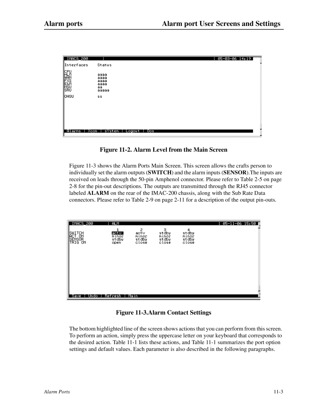
Figure 11-3 shows the Alarm Ports Main Screen. This screen allows the crafts person to individually set the alarm outputs (SWITCH) and the alarm inputs (SENSOR).The inputs are received on leads through the 50-pin Amphenol connector. Please refer to Table 2-5 on page 2-8 for the pin-out descriptions. The outputs are transmitted through the RJ45 connector labeled ALARM on the rear of the IMAC-200 chassis, along with the Sub Rate Data connectors. Please refer to Table 2-9 on page 2-11 for a description of the output pin-outs.
Figure 11-3.Alarm Contact Settings
The bottom highlighted line of the screen shows actions that you can perform from this screen. To perform an action, simply press the uppercase letter on your keyboard that corresponds to the desired action. Table
Alarm Ports |