Part Number MN/CRS300.IOM
CRS-300
Page
Part Number MN/CRS300.IOM Revision March 16
This page is intentionally blank
Table of Contents
Chapter
3.3
10.1
Switch Configuration
Select Monitor
Appendix B. Addressing Scheme Information
Tables
Figures
Data Cable Connection Example CRS-300 to CDM-570/570L
Figure B-3. CRS-300
Xiv
About this Manual
Preface
Trademarks
Conventions and References
Metric Conversion
Recommended Standard Designations
Low Voltage Directive LVD
Safety Compliance
EN55024 1998 Compliance
Federal Communications Commission FCC
Limitations of Warranty
Warranty Policy
Exclusive Remedies
Online Customer Support
Customer Support
Overview
Introduction
CRS-300 110 Redundancy Switch Revision Introduction
Addressing Scheme Information
CRS-300 Compatibility Table
CRS-300 Compatibility
Typical Redundancy System-Level Block Diagram
System-Level Block Diagram
CRS-280/280L if Switch Operational Schematic
CRS-280/280L Functional Schematic
CRS-300 Front Panel
Description of CRS-300 Features Front Panel
Modem Interface Cards CDM-570/570L, -600/600L
Rear Panel
RMI Card CDM-570/570L, -600/600L
PL/9579-1
CDM-625 Modem Data Type TMI Type RMI Type
TMI Cards CDM-570/570L, -600/600L
Data Type TMI Type RMI Type
Data Type TMI Type RMI Type Note
TMI Type RMI Type
11. CRS-305 RMI PL/11494-1
RMI Cards CDM-Qx/QxL, -700, -710, -710G, SLM-5650/5650A
14. CRS-315 TMI PL/11493-1
TMI Cards CDM-Qx/QxL, -700, -710, -710G, SLM-5650/5650A
CRS-230 System Controller AS/0377
CRS-350 ESC Switch Description
CRS-240 AC Power Supply AS/0376 CRS-250 DC PL/10458-1
PL/12985-1
CRS-355 UDI
Characteristic Requirement
Summary of Specifications CRS-300 Specifications
TMI
Modem vs. Terrestrial User Data Interface Specifications
CRS-350 Specifications
CRS-280 and CRS-280L Specifications
27. CRS-300 Dimensional Envelope
Dimensional Envelopes
29. CRS-280 70/140 MHz Dimensional Envelope
30. CRS-280L L-Band Dimensional Envelope
MN/CRS300.IOM
Step Procedure
Unpacking and Inspection
Rack Mounting
Typical Rack Mounting Configuration
Introduction
Ethernet Routers vs. Switches
Ethernet Network Overview
Ethernet Configuration Examples
Wired-thru Connection
Wired-around Connection
Ethernet Redundancy with CRS-300
Networking Loop Example
Hub-to-Hub with Standard Traffic using Switches
This page is intentionally blank
Hub-to-Hub with Standard Traffic using Routers
Hub-to-Hub with Standard Traffic using Routers
MN/CRS300.IOM
MN/CRS300.IOM
MN/CRS300.IOM
10. Point-to-Multipoint using Routers
11. Wired-thru for Point-to-Multipoint with Routers
13. Point-to-Multipoint using Switches
MN/CRS300.IOM
MN/CRS300.IOM
Overview
Cables and Connections
MN/CRS300.IOM
Switch-to-Switch Connections
CRS-300 to CRS-350 and CRS-280/280L Connection
Switch-to-Switch Connections
CRS-300 to CRS-280/280L Connection
CRS-300 to CRS-350 Connection
Control Cable Connection Example for CRS-300 Æ CRS-280
Control Cable Connection Example for CRS-300 ÆCRS-280L
Control Cable Connection Example for CRS-300 Æ CRS-350
MN/CRS300.IOM
MN/CRS300.IOM
MN/CRS300.IOM
CDM-570/570L Modem Connections
CDM-570/570L Modem Connections
Control and Data Connections CRS-300 to Modems
User Data Connections CRS-300 to User
Data Cable Connection Example CRS-300 to CDM-570/570L
MN/CRS300.IOM
CDM-600/600L Modem Connections
CDM-600/600L Modem Connections
Data Cable Connection Example CRS-300 to CDM-600/600L
User ESC Data Connections CRS-350 to User
ESC Data Connections CRS-350 to Modems
Cabling Example for CRS-350 to CDM-600/600L
MN/CRS300.IOM
CDM-625 Modem Connections
CDM-625 Modem Connections
1 RMI/TMI Limitations and Considerations
Carrier-in-CarrierCnC Data Connections
CDM-625 to CDM-625 CnC Cable Connection Example
CDM-625 Cable Usage RMI/TMI
Control and Data Connections CRS-300 to Modem
3.2 G.703 Balanced / Unbalanced Data Connections
When using the CRS-330 or CRS-340 TMIs as shown in Figure
ASI Data Connections
EIA-422 Data Connections
Hssi Data Connections
Lvds Data Connections
Quad E1 Data Connections
Ethernet Data Connections
Ethernet Data Connection Wired-thru Method No Sub-Mux
Ethernet Data Connection Wired-around Method Sub-Mux
Connections shown for RMI and TMIs 1, 3, 5, 7, and 9 only
Connections shown for RMI and TMIs 1, 3, 5, 7, and 9 only
Connections shown for RMI and TMIs 1, 3, 5, 7, and 9 only
Connections shown for RMI and TMIs 1, 3, 5, 7, and 9 only
ESC Data Connections CRS-350 to User
Operation of the CDM-625 in CDM-600/600L Emulation Mode
Select Utility Æ Em Æ Emulation Mode
Data Connections CRS-300 to User
14. Cabling Example for CRS-350 to CDM-625
Normal CDM-625 Emulate CDM-600, Emulate CDM-600L
Connections shown for RMI and TMIs 1, 3, 5, and 7 only
MN/CRS300.IOM
CDM-Qx/QxL Modem Connections
EIA-485 Connections CRS-300 to Modems
CDM-Qx/QxL Modem Connections
16. EIA-485 Multi-drop Cabling Example CRS-300 to CDM-Qx/QxL
Traffic Data Connections CRS-300 to Modems
Control Y-Cable Connections CRS-300 to Modems
User Data Connections CRS-300 to User
Connections shown for RMI and TMI 1 only
Connections shown for RMI and TMI 1 only
Connections shown for RMI and TMI 1 only
Connections shown for RMI and TMI 1 only
Connections shown for RMI and TMI 1 only
CDM-700 Modem Connections
CDM-700 Modem Connections
Interface Combinations
CDM-700 Interface Card Combinations
Serial Traffic Data Connections CRS-300 to Modems
Control Cable Connections CRS-300 to Modems
Wired-thru Connections
Wired-around Connections
Ethernet Traffic Data Connections CRS-300 to Modems
Connections shown for RMI and TMIs 1, 3, and 8 only
Connections shown for RMI and TMIs 3 and 8 only
24. CDM-700 IP Connections Wired-thru Example #1
25. CDM-700 IP Connections Wired-thru Example #2
26. CDM-700 IP Connections Wired-around Example #1
27. CDM-700 IP Connections Wired-around Example #2
CDM-710 Modem Connections
CDM-710 Interface Card Combinations
CDM-710 Modem Connections
Control Cable Connections CRS-300 to Modems
28. Control and Data Cables Example #1 CRS-300 to CDM-710
29. Control and Data Cables Example #2 CRS-300 to CDM-710
MN/CRS300.IOM
CDM-710G Modem Connections
CDM-710G Interface Card Combinations
CDM-710G Modem Connections
Control Cable Connections CRS-300 to Modems
30. Control and Data Cables Example #1 CRS-300 to CDM-710G
31. Control and Data Cables Example #2 CRS-300 to CDM-710G
MN/CRS300.IOM
SLM-5650/5650A Modem Connections
10.1 RMI/TMI Limitations and Considerations
SLM-5650/5650A Modem Connections
Ethernet Bridge Mode via the Optional GbE Interface
Ethernet Bridge Mode via the Optional NP Interface
Ethernet Traffic Data Connections
User Data Connections CRS-300 to User
Connections shown for RMI & TMIs 1, 3, and 8 only
Connections shown for RMI & TMIs 4 and 7 only
Connections shown for RMI & TMIs 1 and 3 only
35. Cabling Example for CRS-350 to SLM-5650/5650A
If Cable Connections
If Cable Connections Single Transponder without CRS-280/280L
If Cable Connections
36. if Cabling Example 1 Single Transponder Configuration
Multiple Transponder if Connections Using if Switch
From the Redundant Modem
From the Tx Traffic Modems
37. Multiple Transponder if Connection Cabling Example
MN/CRS300.IOM
MODEM, RMI/TMI, and Switch Configuration
Modem Modem Firmware Version GigE Firmware Version
Modem Configuration Modem Power
Flash Updating Modem Operational Configuration
Modem Firmware and Hardware Requirements
Config Æ Remote RS-232, 9600 baud, format 8-N-1
Switch to CDM-625 Redundancy Configuration
Select Configuration Æ CnC Æ PMSI-control
CDM-625 Redundancy Configuration with Carrier-in-Carrier
Config Æ AUX Redundancy Mode Æ ENA/DIS set to Enable
Step Procedure
Config Æ Mode Æ Interface Æ Gigabit Ethernet
CDM-Qx/QxL Serial Communication Configuration
Switch to CDM-Qx/QxL Redundancy Configuration
CDM-Qx/QxL / CRS-300 EIA-485 Scheme
Jumper JMP1 Front view Side view
RMI Card Configuration Reference
RMI JMP1 Factory-configured Jumper Settings
‘JMP1’ Jumper Setting AS Shipped CRS-305
EIA-530 Interfaces via the CRS-316 TMI
TMI Card Configuration Reference
CDM-625 CSB to RSB Pin 1 to Pin
CRS-316 Jumper ‘JP1’ Settings
CRS-316 Jumper ‘JP2’ Settings
CRS-316 Jumper ‘JP3’ through ‘JP6’ Settings
Jumper JP2
Front view Side view
Front view Side view Jumper JP2
DTR to DSR Loop
CRS-320/CRS-340 Jumper Settings
Jumper ‘JP1’ Control Signal Setting Jumpers Settings
Open Circuit None
CRS-336 Hssi or Ethernet TMI Card
Hssi Interfaces via the CRS-336 TMI
CRS-336 Jumper ‘JP2’ Settings
CRS-336 Jumper ‘JP1’ Settings
Jumper J2
CRS-370 Jumper Settings
TA controls TX carrier Installed RR controls CA
Hssi Interface via the CRS-370 TMI
Connect the power cords as follows
Switch Configuration Switch Power
Flash Updating
Firmware File Transfer Procedure
Click on CRS-300hyperlink
Activate Traffic Modems
Flash Update Help
CRS-300 Front Panel Configuration
Monitor Æ COMM-STATE or Monitor Æ SW-ALARMS
Verify Connection To Each Active Modem
Set Operation Mode
Set Holdoff Period
Set Backup Holdoff Period
Set Alarm Masking
Set Restore Holdoff Period
If Switch Control DB-25M Connector
CRS-230 Controller Connectors
Remote Control Connector
2 485 Pass-Through DB-9F Connector
Remote Control Connector DB-9M Connector
Pass-Through User Data Connector
System Alarms Connector
System Alarms DB-25F Connector
EIA-232/422/V.35 Connector
Circuit No 232
EIA-232/422/V.35/LVDS DB-25F Connector CRS-320/340
EIA-232/422/V.35/LVDS Connector
Pin Generic Signal Description Direction EIA-422
KHz IDR ESC Connector
ASI BNC Connectors CRS-325
4 8 kHz IDR Connector RJ-45F CRS-330
ASI Connectors
Balanced G.703 DB-15F Connector CRS-325/330/340
Balanced G.703 Connector
Pin Signal Description Name Direction
10. Unbalanced G.703 Connectors
Unbalanced G.703 BNC Connectors CRS-325/330/340
Unbalanced G.703 4-Port BNC Connectors CRS-345
Unbalanced G.703 Connectors
11. Hssi Connector
Hssi HD-50F Connector CRS-336/370
12 /100/1000 Connector
9 10/100/1000 Ethernet RJ-45F Connector CRS-316/336
Quad E1 RJ-48F Connectors CRS-365
13. Quad E1 Connector Typical Ports 1 through
Pin # Name Direction
Quad E1 DB-9F Connectors CRS-365D
14. Quad E1 Connector J2
15. Quad E1 Connector J3
Introduction
Operation
UP Arrow
Front Panel Keypad
Unit Status LED Indicators
Front Panel LED Indicators Unit Status LED Indicators
Orange
Modem Status LED Indicators
Modem Status LED Indicators
Green
Opening Screen
Front Panel Vacuum Fluorescent Display VFD
CRS-300 Menu Tree
CRS-300 Menu Structure
Sect Menu Branch Description
Select Config Configuration
Select Top-Level Menu
Selection
Config Auto AUTO-OFF or AUTO-ON
Config Manual
Config Options
Config Options Æ ALARM-MASK
Config Remote
Config Active Active Modems
To add an additional Traffic Modem
To remove a Traffic Modem that is not being backed-up
Select Info Information
Info S/N
Info ID
Info Mask Alarm Mask Info
Info Remcont Remote Control Info
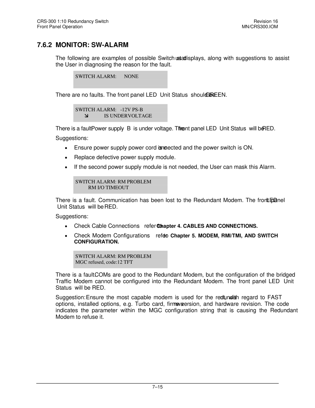
Monitor SW-ALARM
No Error
Switch Alarm Modem Comms PROBLEM, Position
Monitor Comms Communications State
Monitor STORED-EVENTS
STORE/LD Store
Select STORE/LD Store or Load Configuration
Utility Display Display Brightness
Utility SET- RTC Set Real-Time Clock
Utility Test
MN/CRS300.IOM
User/Utility Cables
Appendix A. Cable Drawings
Figure A-1. DCE Conversion Cable EIA-530 to EIA-422/449
EIA-530 to EIA-422 Data Cable
Figure A-2. DCE Conversion Cable EIA-530 to
EIA-530 to V.35 Data Cable
Figure A-3. Switch Programming Cable
Switch Programming Cable
Used for Type
Control Cables
Figure A-4. CDM-625 Control Cable CA-0000069
Control Cable for CDM-625
Standard EIA-485 Multi-drop Shielded Cable, 15X DB-9 Female
Figure A-6. EIA-485 Cable Termination CA/WR11418-1
EIA-485 Cable Termination, 15X DB-9 Male
Figure A-7. EIA-485 Null Modem Cable CA/WR11419-1
EIA-485 Null Modem Cable, DB-9 Male
Optional EIA-485 Multi-drop Ribbon Cable, 15X DB-9 Female
Control ‘Y’ Cable for CDM-Qx and CDM-QxL with CnC→
Figure A-10. CDM-7x0 Control Cable CA/WR12361-1
Control Cable for CDM-700, CDM-710
Figure A-11. SLM-5650/5650A Control Cable CA/WR12136-1
Control Cable for SLM-5650/5650A
Figure A-12. SLM-5650/5650A Control ‘Y’ Cable CA/WR12842-6
Control ‘Y’ Cable for SLM-5650/5650A to CRS-300
Control / if / Data Cables & Accessories
CRS-300 110 Redundancy Switch
EIA-232/422, EIA-530 Control and Data Cable, DB-25
Figure A-14. Balanced G.703 Data Cable CA/WR11999-6
Balanced G.703 Data Cable for CDM-570/570L, DB-15
Figure A-15. Balanced G.703 Data Cable CA/WR9038-6
Balanced G.703 Data Cable, DB-15
Figure A-16. Audio Data Cable CA/WR9932-1
Audio Data Cable, DB-9
Figure A-17. CDM-625 Bal G.703 Data Cable CA-0000072
Balanced G.703 Data Cable for CDM-625
Figure A-18. CDM-625 Quad E1 ‘Y’ Cable CA-0000073
Quad E1 ‘Y’ Data Cable for CDM-625
ASI / Balanced G.703 / if Cable, BNC 75Ω
Overhead Data Cable for CDM-625
Figure A-21. Hssi Data Cable CA/WR9189-6
Hssi Data Cable, HD-50 Male
Figure A-22. CDM-Qx / QxL Quad E1 Data Cable CA/WR13018
Quad E1 Data Cable for CDM-Qx / QxL
MHz Category 5E Patch Cable Specs
Quad E1 / Gigabit Ethernet RJ-48 Connector Cable
Figure A-24. CDM-700 G.703 Data Cable CA/RF12278-1
12 G.703 Data Cable for CDM-700
Figure A-25. CDM-700 G.703 Data Cable CA/RF12279-1
13 G.703 Data Cable for CDM-700
If Cable, BNC 50Ω
Figure A-27. Ethernet Data Cable for CDM-625 CA-0000121
Ethernet Data Cable for CDM-625
MN/CRS300.IOM
Figure A-29. Quad E1 Data Cable for CDM-625 CA-0000136
Quad E1 Data Cable for CDM-625, DB-9
Figure A-30. Quad E1 Data Cable for CDM-625 CA-0000163
Quad E1 Data Adapter Cable for CDM-625
Figure A-31. Quad E1 Data Cable for CDM-625 CA-0000164
RJ-48 DB-15M
20 T1/E1 Adapter for CDM-570/570L, -600/600L
Introduction to Addressing
Appendix B. Addressing Scheme Information
Switch Addresses
Modem and Transceiver Addresses
Abbreviation Explanation
MN/CRS300.IOM
MN/CRS300.IOM
MN/CRS300.IOM
MN/CRS300.IOM
MN/CRS300.IOM
MN/CRS300.IOM
MN/CRS300.IOM
This page is intentionally blank
For CDM-570/570L, CDM-600/600L, CDM-625 modems
Setting Up Modems
M&C Applications
Setting Up Transceivers
EIA-485
Appendix C. Remote Control
EIA-232
Basic Protocol
Rules for Remote Serial Communications with the CRS-300
Delimiter
Packet Structure
Start of Packet
Target Address
Instruction Code
Address Delimiter
Instruction Code Qualifier
Ascii code
Ascii code Ascii Code
Remote Commands and Queries
Optional Message Arguments
End of Packet
Response to Command Target-to-Controller
Command
Parameter Type Code Qualifier Audio Alarm
Arguments for Command or Response to Query
Example S300
Parameter Type Code Qualifier Config Load
FLT=rAaBbCcDdEeFfmi
See Description
Arguments
Example NUE=98
MOD=xxx
RNE?
Parameter Type Code Qualifier
Example SDT=1
Parameter Type Code Qualifier Switch Alarm
Mask Arguments for Command or Response to Query
SAM=x
SNO?
XMI=xxxxxxxxxxy
Command Arguments for
Temperature Conversions
Units of Weight
Units of Length
480 333 2200 Phone 480 333 2161 FAX