Connector | System Installation |
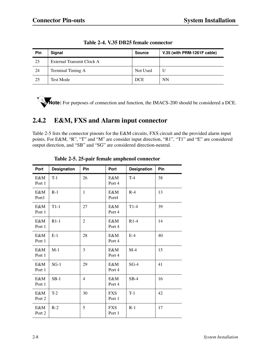
Table 2-4. V.35 DB25 female connector
Pin | Signal | Source | V.35 (with |
|
|
|
|
23 | External Transmit Clock A |
|
|
|
|
|
|
24 | Terminal Timing A | Not Used | U |
|
|
|
|
25 | Test Mode | DCE | NN |
|
|
|
|
![]() Note: For purposes of connection and function, the
Note: For purposes of connection and function, the
2.4.2E&M, FXS and Alarm input connector
Table
Table 2-5. 25-pair female amphenol connector
Port | Designation | Pin | Port | Designation | Pin | |
|
|
|
|
|
| |
E&M | 26 | E&M | 38 | |||
Port 1 |
|
| Port 4 |
|
| |
|
|
|
|
|
| |
E&M | 1 | E&M | 13 | |||
Port1 |
|
| Port4 |
|
| |
|
|
|
|
|
| |
E&M | 27 | E&M | 39 | |||
Port 1 |
|
| Port 4 |
|
| |
|
|
|
|
|
| |
E&M | 2 | E&M | 14 | |||
Port 1 |
|
| Port 4 |
|
| |
|
|
|
|
|
| |
E&M | 28 | E&M | 40 | |||
Port 1 |
|
| Port 4 |
|
| |
|
|
|
|
|
| |
E&M | 3 | E&M | 15 | |||
Port 1 |
|
| Port 4 |
|
| |
|
|
|
|
|
| |
E&M | 29 | E&M | 41 | |||
Port 1 |
|
| Port 4 |
|
| |
|
|
|
|
|
| |
E&M | 4 | E&M | 16 | |||
Port 1 |
|
| Port 4 |
|
| |
|
|
|
|
|
| |
E&M | 30 | FXS | 42 | |||
Port 2 |
|
| Port 1 |
|
| |
|
|
|
|
|
| |
E&M | 5 | FXS | 17 | |||
Port 2 |
|
| Port 1 |
|
| |
|
|
|
|
|
| |
|
|
|
|
|
|
System Installation |
