Getting Started
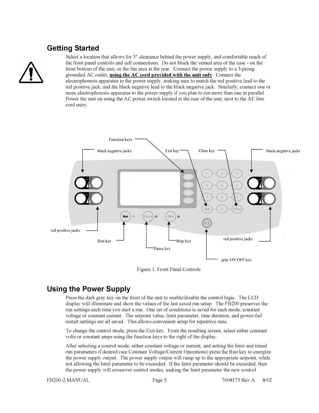
Select a location that allows for 3" clearance behind the power supply, and comfortable reach of the front panel controls and cell connections. Do not block the vented area of the case - on the front bottom of the unit, or the fan area at the rear. Connect the power supply to a
Function keys
black negative jacks | Exit key |
| Clear key |
|
|
| black negative jacks |
| |||||||
|
|
|
red positive jacks
Run key | Stop key |
| red positive jacks |
|
| ||
| Pause key |
|
|
|
|
| gray ON/OFF key |
|
|
|
Figure 1. Front Panel Controls
Using the Power Supply
Press the dark gray key on the front of the unit to enable/disable the control logic. The LCD display will illuminate and show the values of the last saved run setup. The FB200 preserves the run settings each time you start a run. One set of conditions is saved for each mode, constant voltage or constant current. The setpoint value, limit parameter, time duration, and
To change the control mode, press the Exit key. From the resulting screen, select either constant volts or constant amps using the function keys to the right of the display.
After selecting a control mode, either constant voltage or current, and setting the limit and timed run parameters if desired (see Constant Voltage/Current Operations) press the Run key to energize the power supply output. The power supply output will ramp up to the appropriate setpoint, while not allowing the limit parameter to be exceeded. If the limit parameter should be exceeded, then the power supply will crossover control modes, making the limit parameter the new control
Page 5 | 7608175 Rev A 8/02 |
