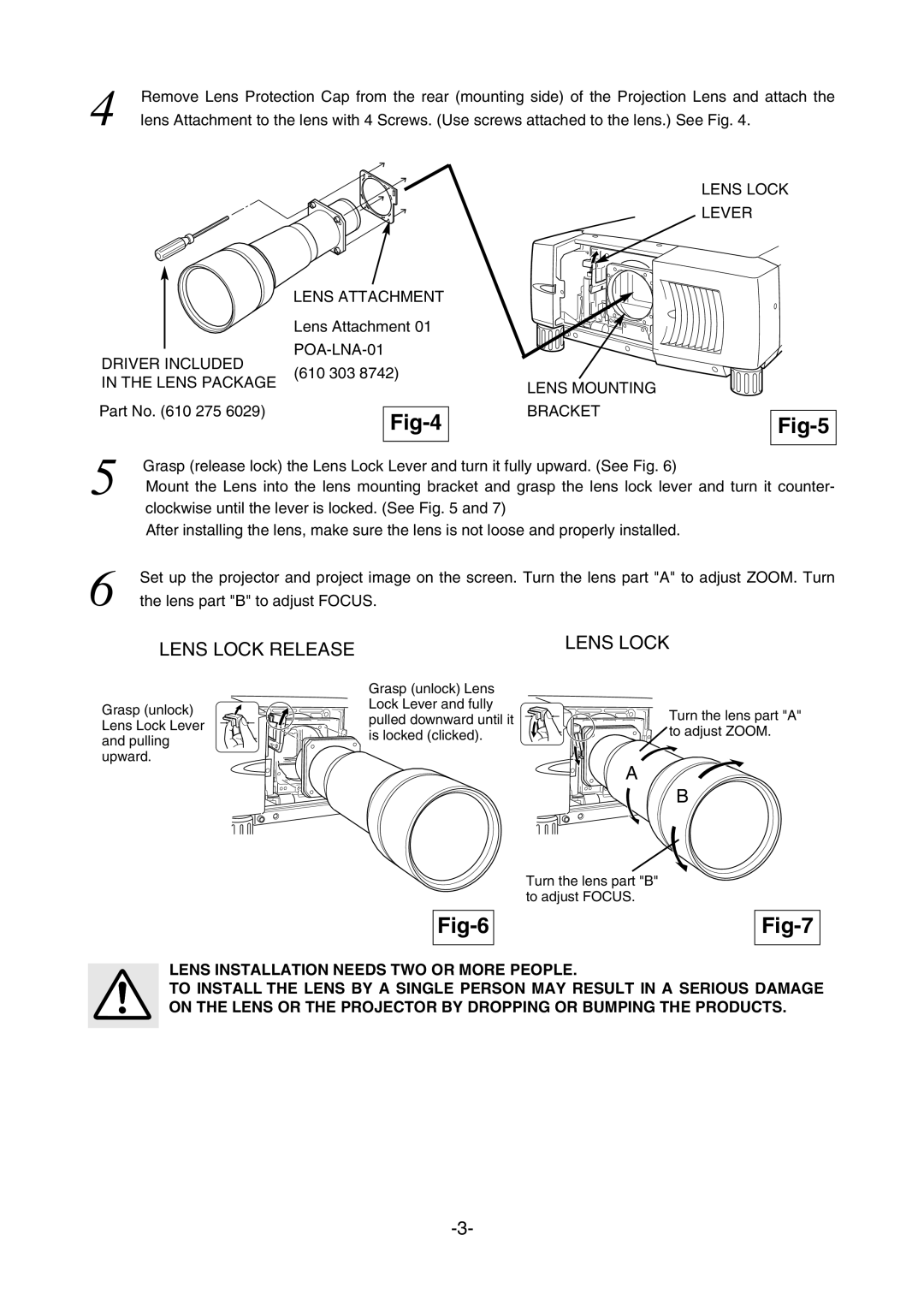
4 | Remove Lens Protection Cap from the rear (mounting side) of the Projection Lens and attach the |
lens Attachment to the lens with 4 Screws. (Use screws attached to the lens.) See Fig. 4. |
LENS LOCK
LEVER
| LENS ATTACHMENT |
| |
| Lens Attachment 01 |
| |
DRIVER INCLUDED |
| ||
(610 303 8742) |
| ||
IN THE LENS PACKAGE | LENS MOUNTING | ||
| |||
|
| ||
Part No. (610 275 6029) |
| BRACKET | |
|
|
5 | Grasp (release lock) the Lens Lock Lever and turn it fully upward. (See Fig. 6) |
| |
| Mount the Lens into the lens mounting bracket and grasp the lens lock lever and turn it counter- |
| clockwise until the lever is locked. (See Fig. 5 and 7) |
| After installing the lens, make sure the lens is not loose and properly installed. |
6 | Set up the projector and project image on the screen. Turn the lens part "A" to adjust ZOOM. Turn |
the lens part "B" to adjust FOCUS. |
LENS LOCK RELEASE
| Grasp (unlock) Lens | |
Grasp (unlock) | Lock Lever and fully | |
pulled downward until it | ||
Lens Lock Lever | ||
is locked (clicked). | ||
and pulling | ||
| ||
upward. |
|
LENS LOCK
Turn the lens part "A"
![]() to adjust ZOOM.
to adjust ZOOM.
A
B
Turn the lens part "B" to adjust FOCUS.
Fig-6
Fig-7
LENS INSTALLATION NEEDS TWO OR MORE PEOPLE.
TO INSTALL THE LENS BY A SINGLE PERSON MAY RESULT IN A SERIOUS DAMAGE ON THE LENS OR THE PROJECTOR BY DROPPING OR BUMPING THE PRODUCTS.