ELECTRICAL REQUIREMENTS
I m p o rtant: Use a 14 ga. or heavier extension cord with a maximum length of 100 ft.
Grounding Instructions
This shredder should be grounded while in use to reduce the risk of electric shock to the operator.
The shredder is equipped with a
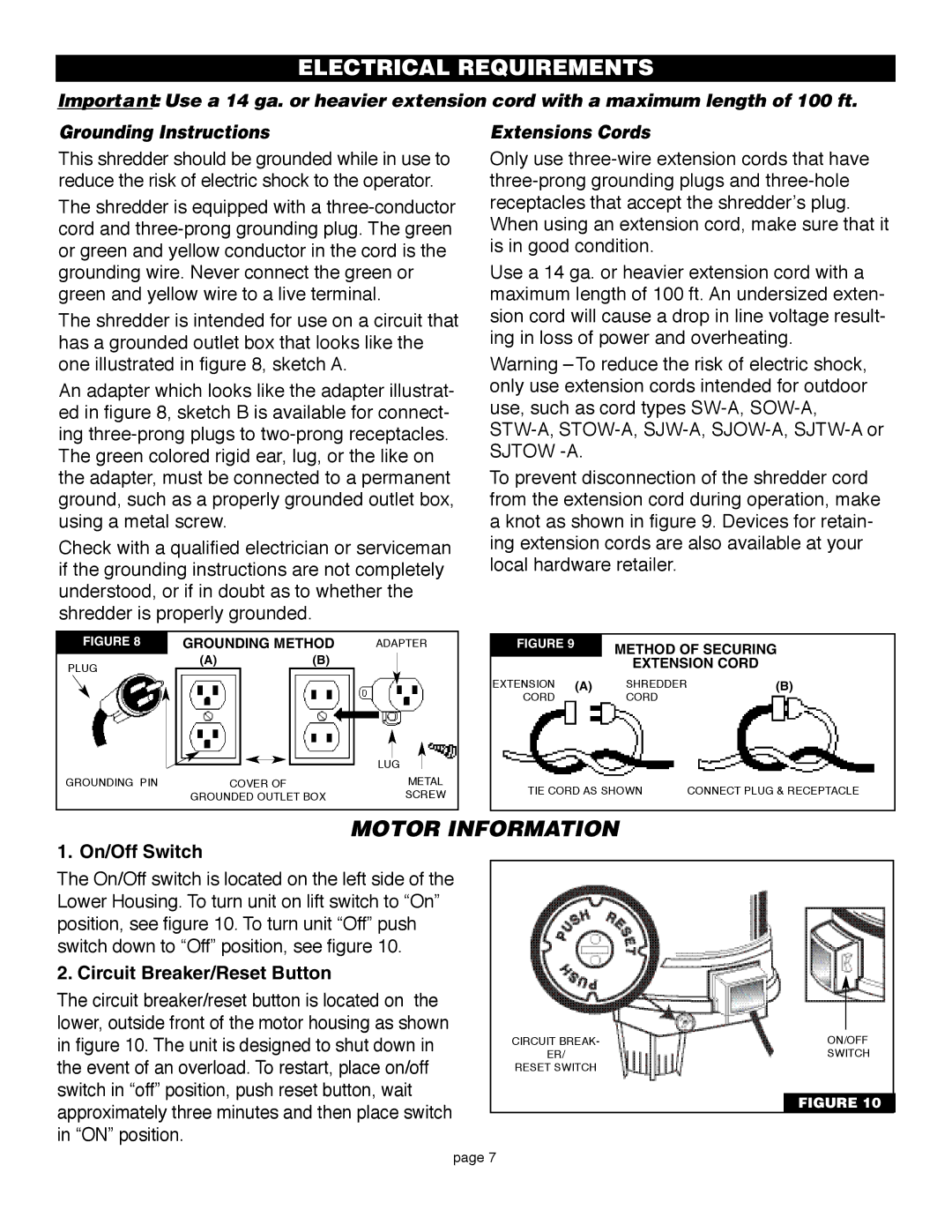
The shredder is intended for use on a circuit that has a grounded outlet box that looks like the one illustrated in figure 8, sketch A.
An adapter which looks like the adapter illustrat- ed in figure 8, sketch B is available for connect- ing
Check with a qualified electrician or serviceman if the grounding instructions are not completely understood, or if in doubt as to whether the shredder is properly grounded.
FIGURE 8 |
|
|
|
| GROUNDING METHOD | ADAPTER | |
|
|
|
|
Extensions Cords
Only use
Use a 14 ga. or heavier extension cord with a maximum length of 100 ft. An undersized exten- sion cord will cause a drop in line voltage result- ing in loss of power and overheating.
Warning – To reduce the risk of electric shock, only use extension cords intended for outdoor use, such as cord types
To prevent disconnection of the shredder cord from the extension cord during operation, make a knot as shown in figure 9. Devices for retain- ing extension cords are also available at your local hardware retailer.
FIGURE 9 | METHOD OF SECURING |
PLUG
(A)(B)
|
| EXTENSION CORD |
|
EXTENSION | (A) | SHREDDER | (B) |
CORD |
| CORD |
|
|
|
|
|
|
|
|
|
|
|
|
|
|
|
|
|
|
| LUG |
| |
| COVER OF |
| METAL | |||
GROUNDING PIN | ||||||
| GROUNDED OUTLET BOX |
| SCREW | |||
TIE CORD AS SHOWN | CONNECT PLUG & RECEPTACLE |
MOTOR INFORMATION
1. On/Off Switch
The On/Off switch is located on the left side of the Lower Housing. To turn unit on lift switch to “On” position, see figure 10. To turn unit “Off” push switch down to “Off” position, see figure 10.
2. Circuit Breaker/Reset Button
The circuit breaker/reset button is located on the lower, outside front of the motor housing as shown in figure 10. The unit is designed to shut down in the event of an overload. To restart, place on/off switch in “off” position, push reset button, wait approximately three minutes and then place switch in “ON” position.
CIRCUIT BREAK- | ON/OFF |
ER/ | SWITCH |
RESET SWITCH |
|
FIGURE 10
page 7