Fluke 1520
Users Manual
Display
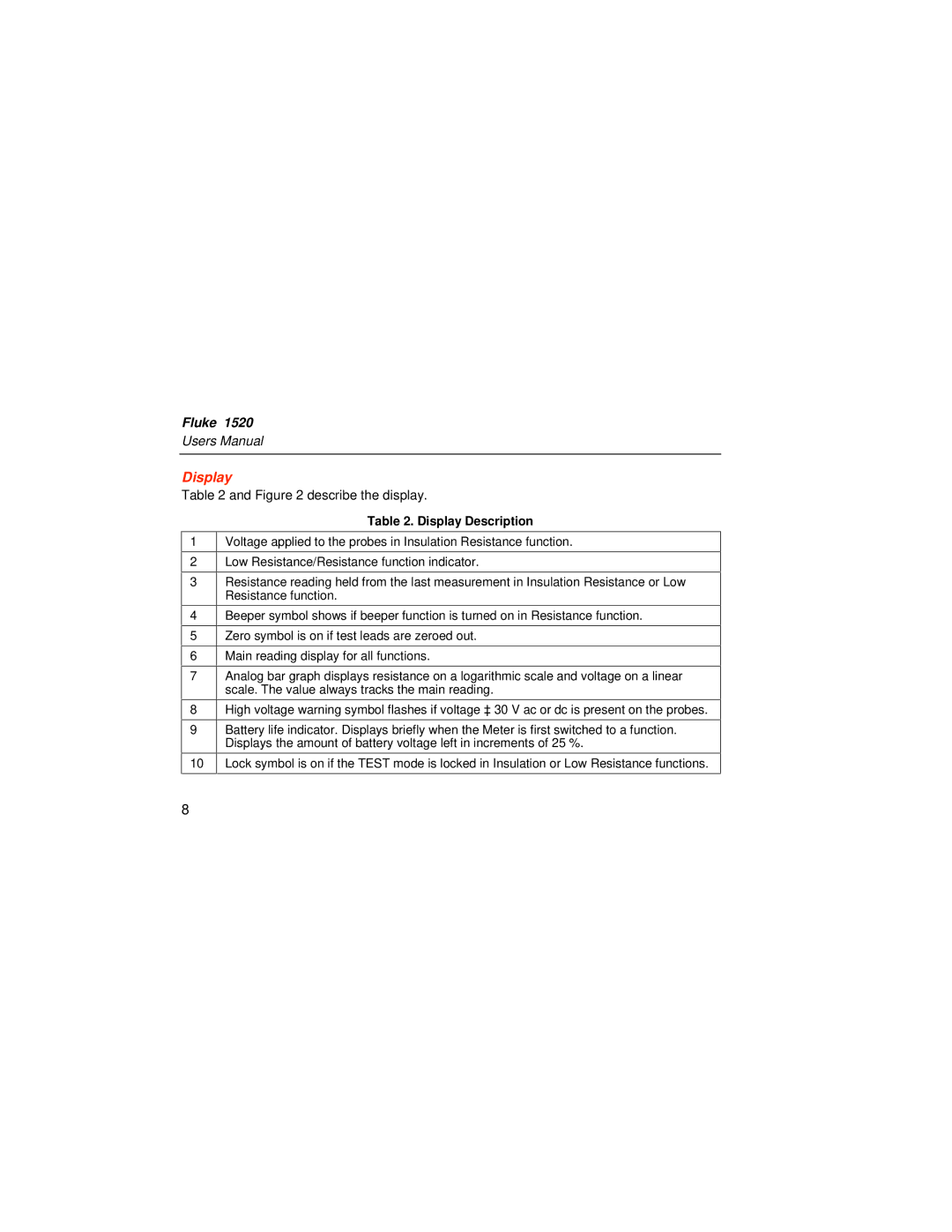
Table 2 and Figure 2 describe the display.
1
2
3
4
5
6
7
8
9
10
Table 2. Display Description
Voltage applied to the probes in Insulation Resistance function.
Low Resistance/Resistance function indicator.
Resistance reading held from the last measurement in Insulation Resistance or Low Resistance function.
Beeper symbol shows if beeper function is turned on in Resistance function.
Zero symbol is on if test leads are zeroed out.
Main reading display for all functions.
Analog bar graph displays resistance on a logarithmic scale and voltage on a linear scale. The value always tracks the main reading.
High voltage warning symbol flashes if voltage ≥ 30 V ac or dc is present on the probes.
Battery life indicator. Displays briefly when the Meter is first switched to a function. Displays the amount of battery voltage left in increments of 25 %.
Lock symbol is on if the TEST mode is locked in Insulation or Low Resistance functions.
8