Manuals
/
Fluke
/
Lawn and Garden
/
Portable Generator
Fluke
271
manual
Effect of the output attenuator, Dc Offset Change * * By Output Level
Models:
271
1
24
34
34
Download
34 pages
58.5 Kb
21
22
23
24
25
26
27
28
Page 24
Image 24
Page 23
Page 25
Page 24
Image 24
Page 23
Page 25
Contents
Getting Started Manual
Programmable 10 MHz DDS Function Generator
LIMITED WARRANTY AND LIMITATION OF LIABILITY
To register your product online, visit register.fluke.com
Safety
Getting Started Manual
Safety continued
The following symbols are used on the instrument and in this manual
Terminal connected to chassis ground Mains supply OFF Mains supply ON
Alternating current Warning - hazardous voltages may be present
Page
EMC Compliance
Emissions
Immunity
e EN61000-4-5 1995 Surge 0.5 kV line to line, 1 kV line to ground
Table of Contents
Title
viii
AUX OUT
Getting Started
Introduction
Before You Start
Mains Supply Voltage
Externally Applied Voltages
Controls and Connections
Getting Started
Figure 1. Model 271 Front Panel
shx0001f.gif
The Liquid Crystal Display
Controls
Function Keys
FIELD and DIGIT Keys and the Rotary Control
Numeric, Units and SET Keys
MODE Keys
UTILITIES Keys
OUTPUT Key
RECALL and REMOTE
Front Panel Inputs and Outputs
EXT TRIG
MAIN OUT
AUX OUT
Rear Panel Connectors
CLOCK IN/OUT
VCA IN
SYNC OUT
RS232 and GPIB Interface Connectors
TRIG/SWEEP OUT
Using the Instrument
Plug in and switch on the instrument
Starting up
Check the LCD Display
Generating Continuous Signals
Set a frequency, for example 12.5 kHz
FREQ=12.50000kHz VhiZ=+20.0 Vpp 50Ω DC=+0.00mV +0.00mV
SYM=50.0% 50.0%
Set the amplitude to +10 dBm
Have a look at some other waveforms
Change the dc offset
=80.00000us
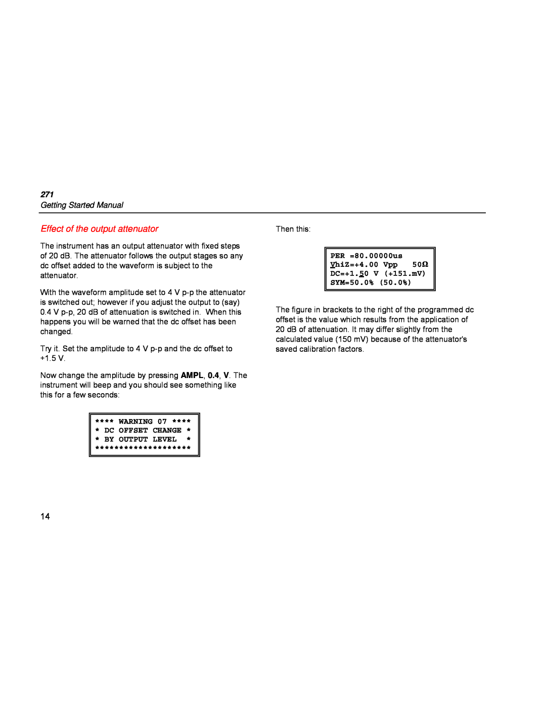
Effect of the output attenuator
DC OFFSET CHANGE * * BY OUTPUT LEVEL
PER =80.00000us VhiZ=+4.00 Vpp 50Ω DC=+1.50 V +151.mV SYM=50.0% 50.0%
Adjusting the phase
SOURCE=EXT TGEN=1.00ms 1.000kHz BURST COUNT= PHASE=+000 +000
SOURCE=EXT TGEN=1.00ms 1.000kHz BURST COUNT= PHASE=+116 +116
Asymmetric waveforms
Generating Swept Signals
TRIG/SWEEP OUT signal
MODE=BEG-END LAW=LOG RAMP TIME=0.05 s TRIG SRC=CONTINUOUS MORE
MODE=BEG-END LAW=LOG RAMP TIME=5.00 s TRIG SRC=CONTINUOUS MORE
BEG FRQ=261.6000 Hz END FRQ=1.108700kHz MARK FRQ=523.3000 Hz MORE
SOURCE=EXT TGEN=1.00ms 1.000kHz BURST COUNT=0001 PHASE=+000 +000
PHASE=+000 +000
Generating a Triggered Burst
FREQ=2.000000kHz VhiZ=+20.0 Vpp 50Ω DC=+0.00mV +0.00mV
FSK Mode
Special Waveforms
Staircases
FREQ A=800.0000 Hz FREQ B=1.200000kHz SOURCE=TGEN FREE
Figure 2. 625-line PAL TV Signal
step
name
start µs
amplitude
VALS=ABS AUTO=YES STEP=01 ACTIVE LENGTH=0256 LEVEL=+000
VALS=ABS AUTO=YES STEP=08 ACTIVE LENGTH=0005 LEVEL=+153
Saving and Recalling Settings
Arbitrary Waveforms
RECALL ARB No SINX/X ENTER TO EXECUTE
RECALL ARB No ARB 03 IS EMPTY
Other Functions and Waveforms
Top
Page
Image
Contents