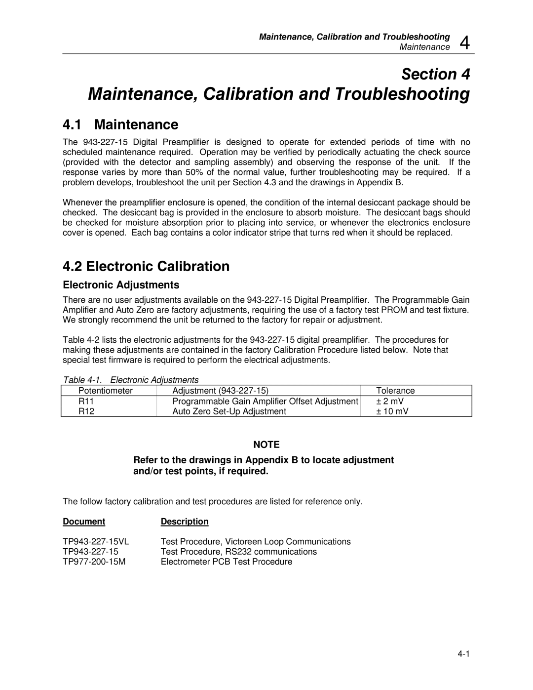
943-227-15, 943-27 specifications
The Fluke 943-27 and Fluke 943-227-15 are advanced electrical testing tools designed to meet the demands of professionals in industrial and commercial settings. Recognized for their accuracy and reliability, these devices come loaded with essential features tailored to ensure optimal performance during electrical measurements.The Fluke 943-27 is a compact yet powerful multimeter that excels in providing precise voltage and current readings. It is equipped with a large, backlit display that ensures visibility in low-light environments. The device supports a wide range of testing parameters, including AC and DC voltage, resistance, continuity, and capacitance measurements, making it invaluable for troubleshooting electrical circuits.
On the other hand, the Fluke 943-227-15 offers additional capabilities, including advanced data logging features. This multimeter allows users to record and analyze measurements over time, which is particularly useful for identifying intermittent issues in electrical systems. Its connectivity options enable seamless data transfer to a computer or mobile device, facilitating easy documentation and reporting.
Both models illustrate a robust construction built to endure tough working conditions. They meet stringent safety standards, which is critical for protecting users from electrical hazards. The ergonomic design ensures comfort during prolonged use, and features like overmolding enhance grip and durability.
One of the standout technologies in these multimeters is Fluke’s True-RMS measurement capability. This feature ensures accurate readings of non-linear loads, which are common in modern electrical systems with variable frequency drives and other electronic devices. Additionally, the built-in low-pass filter technology reduces noise in measurements, ensuring precision even in environments with significant electrical interference.
The Fluke 943-27 and 943-227-15 are also designed to be user-friendly. They feature intuitive controls and a straightforward user interface, allowing technicians to navigate functions effortlessly. The ability to perform automatic ranging simplifies measurements, eliminating the potential for errors when setting the range manually.
In conclusion, the Fluke 943-27 and 943-227-15 represent essential tools for electrical technicians who require versatility, accuracy, and durability in their testing equipment. With advanced features, reliable technologies, and a user-centric design, these multimeters not only meet but exceed the expectations of professionals in the field.
