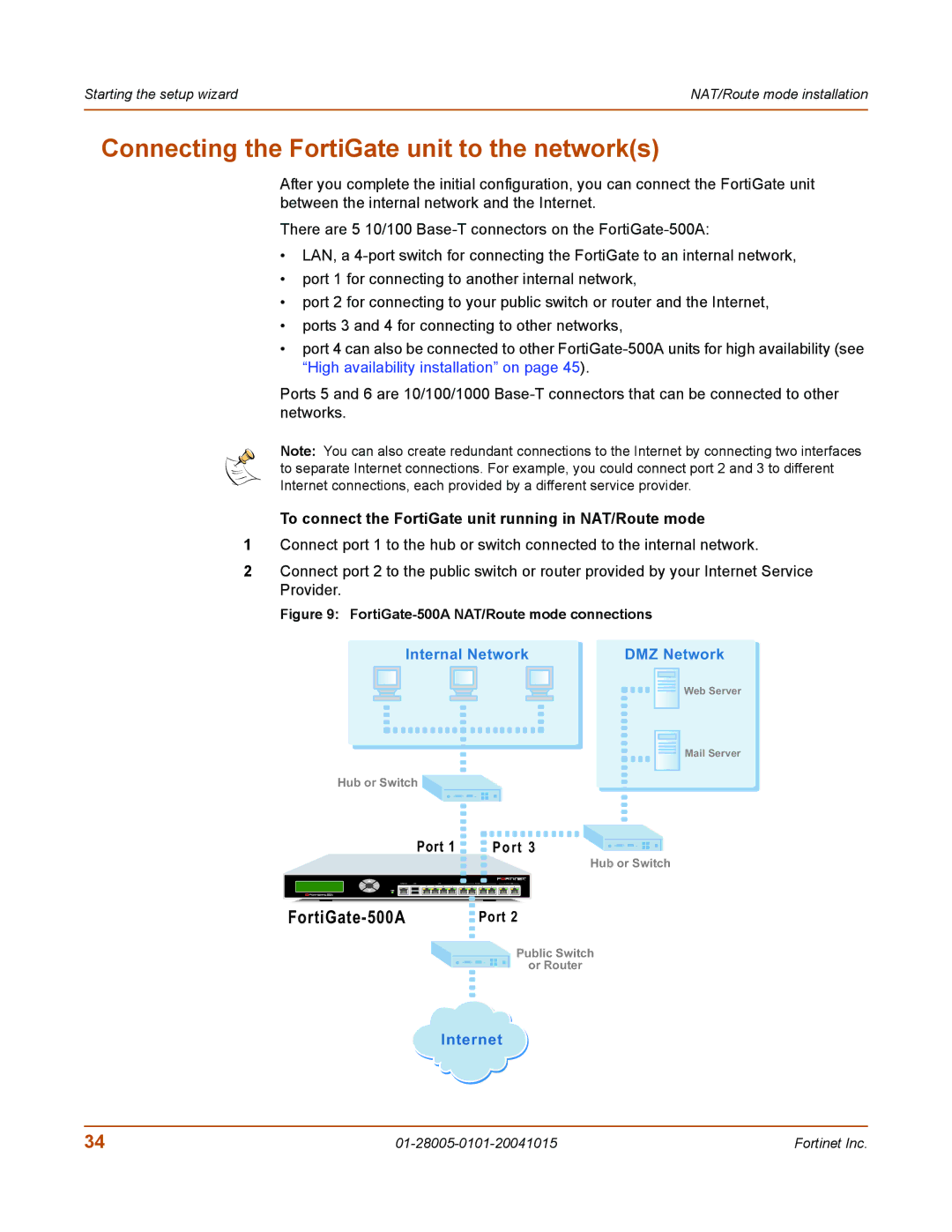
500A, Network Router, 127, FORTIGATE specifications
Fortinet FortiGate 127 is an advanced network security appliance designed to deliver comprehensive protection to organizations while ensuring seamless network performance. As a part of Fortinet's leading next-generation firewall (NGFW) offerings, the FortiGate 127 integrates various essential features and technologies that are critical for modern network security.One of the standout features of the FortiGate 127 is its ability to perform deep packet inspection. This technology enables the device to analyze and filter network traffic, identifying and mitigating threats such as malware, viruses, and intrusions in real-time. With a robust Threat Intelligence system, FortiGate utilizes FortiGuard Labs to provide continuous updates on emerging threats, equipping organizations with the necessary defense against sophisticated cyberattacks.
Another key technology included in the FortiGate 127 is integrated secure SD-WAN functionality. This feature allows organizations to optimize their wide-area network (WAN) connections, enhancing performance and reducing costs through intelligent traffic routing and real-time application visibility. By leveraging software-defined capabilities, businesses can ensure efficient use of their bandwidth, prioritize critical applications, and maintain high levels of uptime.
The FortiGate 127 also excels in providing advanced VPN support. With multiple VPN protocols such as IPsec and SSL, users can establish secure remote connections, facilitating safe access to corporate resources from anywhere. This is particularly important in today's remote work environment, where secure connectivity is essential for maintaining productivity while protecting sensitive data.
In terms of performance, the FortiGate 127 is equipped with high throughput capabilities, ensuring it can handle extensive network traffic without compromising speed or efficiency. Its multi-core architecture allows for parallel processing, which enhances overall performance and responsiveness.
Additionally, the device features an intuitive and user-friendly interface, enabling IT teams to easily manage and configure network policies. With centralized management options, administrators can efficiently oversee multiple FortiGate devices within their network, ensuring optimal visibility and control.
Overall, the Fortinet FortiGate 127 Network Router is a powerful solution for organizations seeking to bolster their security posture. With its combination of deep packet inspection, integrated SD-WAN functionality, advanced VPN support, and high-performance capabilities, it stands out as a vital asset in the modern cybersecurity landscape. It is an ideal choice for businesses aiming to protect their networks from the ever-evolving threat landscape while maintaining operational efficiency.

