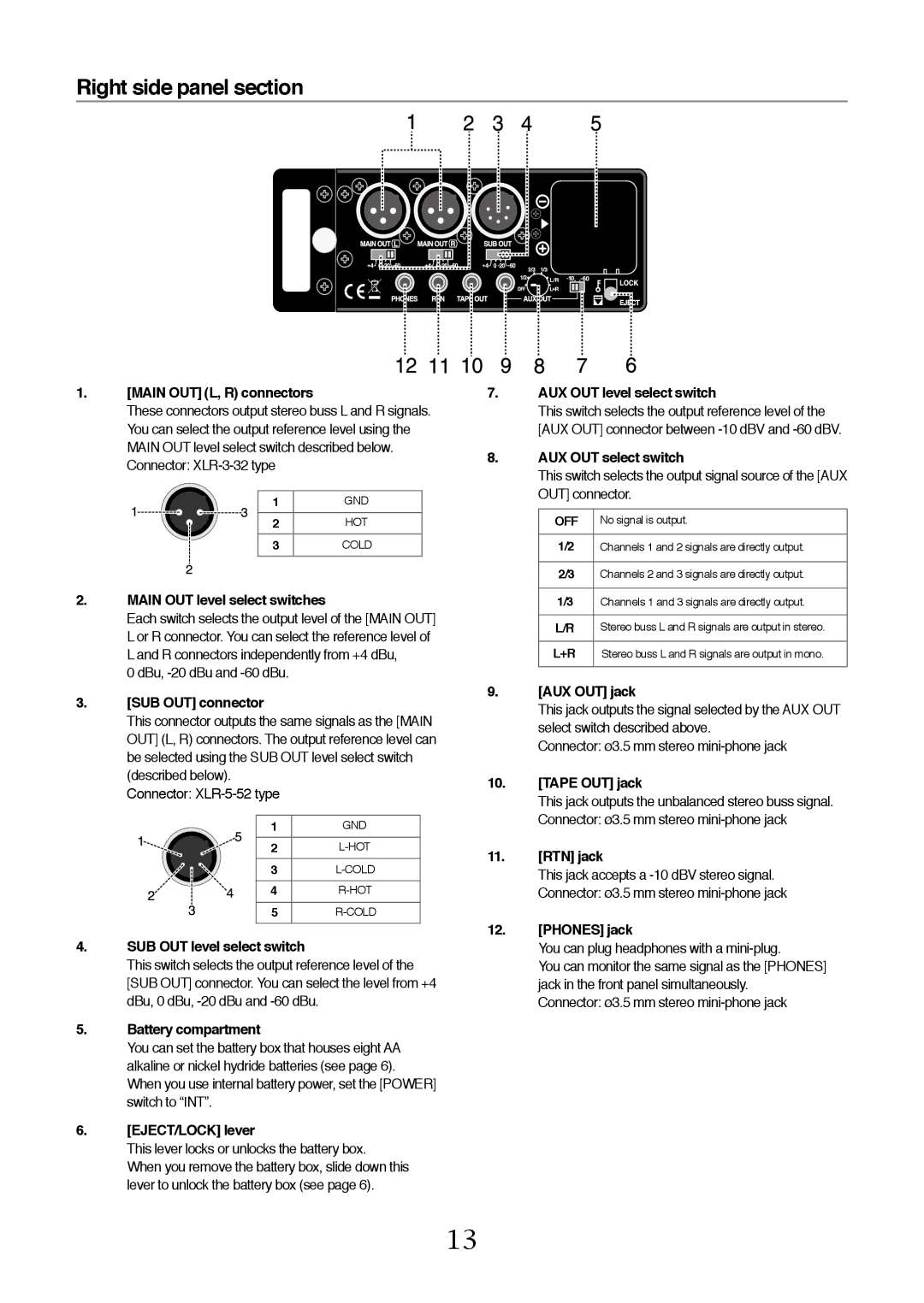
Right side panel section
1.[MAIN OUT] (L, R) connectors
These connectors output stereo buss L and R signals. You can select the output reference level using the MAIN OUT level select switch described below. Connector:
1 | GND |
2 | HOT |
3 | COLD |
2. MAIN OUT level select switches
Each switch selects the output level of the [MAIN OUT] L or R connector. You can select the reference level of L and R connectors independently from +4 dBu,
0 dBu,
3. | [SUB OUT] connector |
|
| |
| This connector outputs the same signals as the [MAIN | |||
| OUT] (L, R) connectors. The output reference level can | |||
| be selected using the SUB OUT level select switch | |||
| (described below). |
|
| |
| Connector: |
|
| |
|
|
|
| |
|
| 1 | GND |
|
|
| 2 |
| |
|
| 3 |
| |
|
| 4 |
| |
|
| 5 |
| |
4. SUB OUT level select switch
This switch selects the output reference level of the [SUB OUT] connector. You can select the level from +4 dBu, 0 dBu,
5. Battery compartment
You can set the battery box that houses eight AA alkaline or nickel hydride batteries (see page 6). When you use internal battery power, set the [POWER] switch to “INT”.
6. [EJECT/LOCK] lever
This lever locks or unlocks the battery box.
When you remove the battery box, slide down this lever to unlock the battery box (see page 6).
7.AUX OUT level select switch
This switch selects the output reference level of the [AUX OUT] connector between
8.AUX OUT select switch
This switch selects the output signal source of the [AUX OUT] connector.
OFF | No signal is output. |
|
|
1/2 | Channels 1 and 2 signals are directly output. |
|
|
2/3 | Channels 2 and 3 signals are directly output. |
|
|
1/3 | Channels 1 and 3 signals are directly output. |
|
|
L/R | Stereo buss L and R signals are output in stereo. |
|
|
L+R | Stereo buss L and R signals are output in mono. |
|
|
9.[AUX OUT] jack
This jack outputs the signal selected by the AUX OUT select switch described above.
Connector: ø3.5 mm stereo
10.[TAPE OUT] jack
This jack outputs the unbalanced stereo buss signal. Connector: ø3.5 mm stereo
11.[RTN] jack
This jack accepts a
12.[PHONES] jack
You can plug headphones with a
You can monitor the same signal as the [PHONES] jack in the front panel simultaneously.
Connector: ø3.5 mm stereo
13
