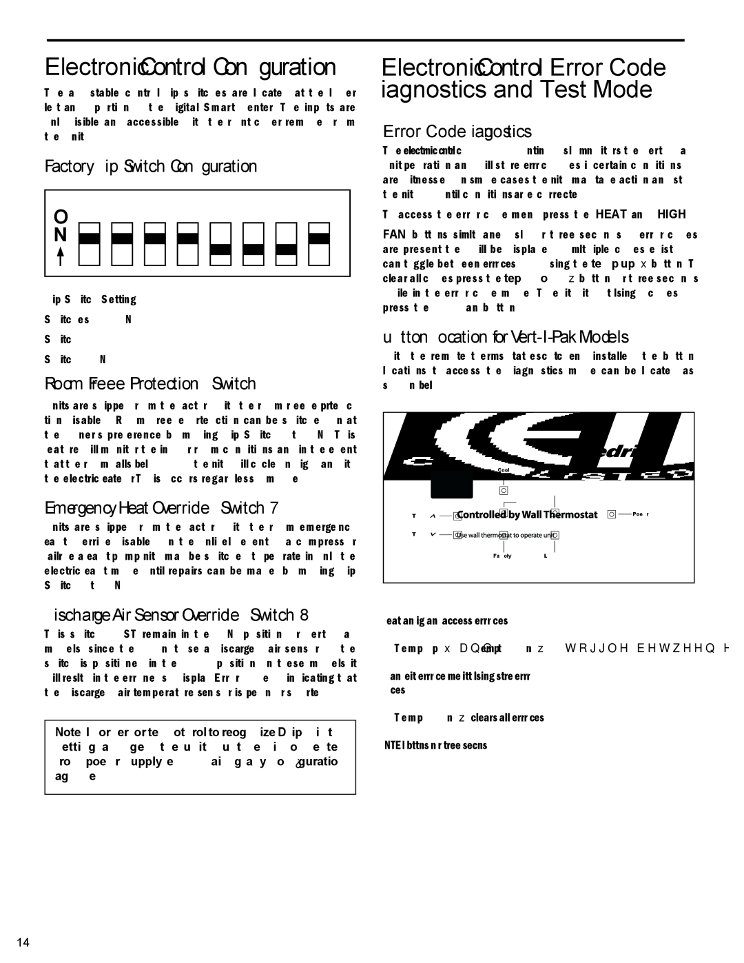
Electronic Control Configuration
The adjustable control dip switches are located at the lower left hand portion of the digital Smart Center. The inputs are only visible and accessible with the front cover removed from the Unit.
Factory Dip Switch Configuration
O | 1 | 2 | 3 | 4 | 5 | 6 | 7 | 8 |
| ||||||||
N |
|
|
|
|
|
|
|
|
|
|
|
|
|
|
|
| |
|
|
|
|
|
|
|
|
|
|
|
|
|
|
|
| ||
|
|
|
|
|
|
|
|
|
|
|
|
|
|
|
|
|
|
|
|
|
|
|
|
|
|
|
|
|
|
|
|
|
|
|
|
|
|
|
|
|
|
|
|
|
|
|
|
|
|
|
|
|
|
Dip Switch Setting
Switches
Switch
Switch 8 ON
Room Freeze Protection – Switch 6
Units are shipped from the factory with the room freeze protec- tion disabled. Room Freeze Protection can be switched on at the owner’s preference by moving Dip Switch 6 to ‘ON’. This feature will monitor the indoor room conditions and in the event that the room falls below 40°F the unit will cycle on high fan with the electric heater. This occurs regardless of mode.
Emergency Heat Override – Switch 7
Units are shipped from the factory with the room emergency heat override disabled. In the unlikely event of a compressor failure a heat pump unit may be switched to operate in only the electric heat mode until repairs can be made, by moving Dip Switch 7 to ‘ON’.
Discharge Air Sensor Override – Switch 8
This switch MUST remain in the “ON” position for
Note: In order for the control to recognize “Dip” switch setting changes, the unit must be disconnected from power supply when making any configuration changes.
Electronic Control Error Code Diagnostics and Test Mode
Error Code Diagnostics
The VPAK electronic control continuously monitors the
To access the error code menu press the ‘HEAT’ and ‘HIGH
FAN’ buttons simultaneously for three seconds. If error codes are present they will be displayed. If multiple codes exist you can toggle between error codes using the temp up ▲ button. To clear all codes press the temp down ▼ button for three seconds while in the error code mode. To exit without losing codes press the ‘Low Fan’ button.
Button Location for Vert-I-Pak Models
With the remote thermostat escutcheon installed, the button locations to access the diagnostics mode can be located as shown below.
Cool |
|
| High fan |
| Heat |
Temp | Power |
Temp |
|
Fan only | Low fan |
*Heat and high fan - access error codes
*Temp up ▲ and temp down ▼ - toggle between error codes
*Low fan - exit error code mode without losing stored error codes.
*Temp down ▼ - clears all error codes
NOTE: Hold buttons down for three seconds.
14
