Pin assignment of internal ports
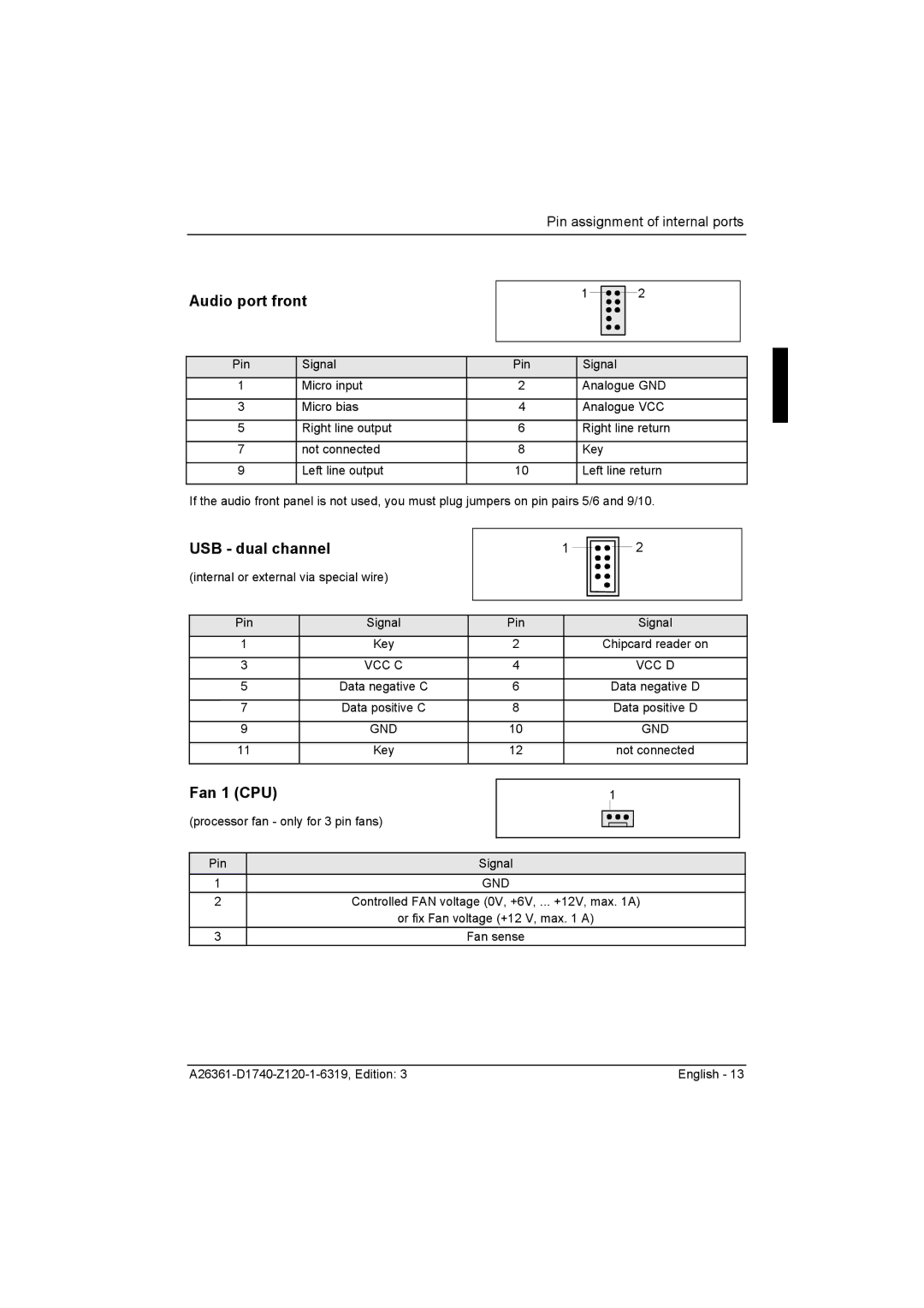
Audio port front
1![]()
![]()
![]()
![]() 2
2
Pin | Signal | Pin | Signal |
1 | Micro input | 2 | Analogue GND |
|
|
|
|
3 | Micro bias | 4 | Analogue VCC |
|
|
|
|
5 | Right line output | 6 | Right line return |
|
|
|
|
7 | not connected | 8 | Key |
|
|
|
|
9 | Left line output | 10 | Left line return |
|
|
|
|
If the audio front panel is not used, you must plug jumpers on pin pairs 5/6 and 9/10.
USB - dual channel
(internal or external via special wire)
1 ![]()
![]()
![]()
![]() 2
2
Pin | Signal | Pin | Signal |
1 | Key | 2 | Chipcard reader on |
|
|
|
|
3 | VCC C | 4 | VCC D |
|
|
|
|
5 | Data negative C | 6 | Data negative D |
|
|
|
|
7 | Data positive C | 8 | Data positive D |
|
|
|
|
9 | GND | 10 | GND |
|
|
|
|
11 | Key | 12 | not connected |
|
|
|
|
Fan 1 (CPU)
(processor fan - only for 3 pin fans)
1
Pin
1
2
3
Signal
GND
Controlled FAN voltage (0V, +6V, ... +12V, max. 1A)
or fix Fan voltage (+12 V, max. 1 A)
Fan sense
English - 13 |