Pin assignment of internal ports
Pin assignment of internal ports
The pin assignment of some internal connections is shown in English in the following.
iSome of the following connectors may be optional!
Front panel
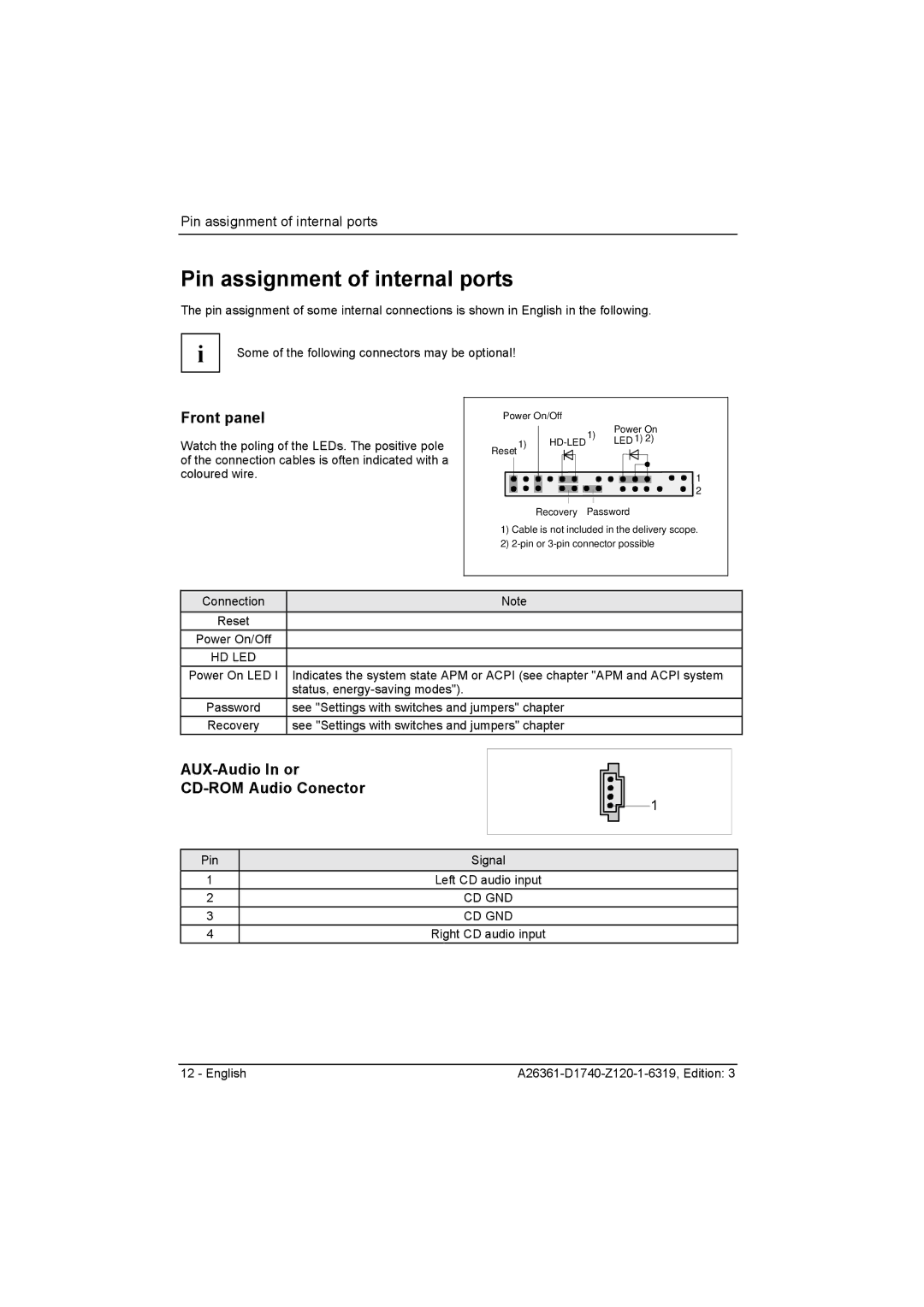
Watch the poling of the LEDs. The positive pole of the connection cables is often indicated with a coloured wire.
Power On/Off |
|
| ||
|
| 1) | Power On | |
Reset 1) |
| LED 1) 2) | ||
| ||||
|
|
| ||
1
2
Recovery Password
1)Cable is not included in the delivery scope.
2)
Connection | Note |
Reset |
|
Power On/Off |
|
HD LED |
|
Power On LED I | Indicates the system state APM or ACPI (see chapter "APM and ACPI system |
| status, |
Password | see "Settings with switches and jumpers" chapter |
Recovery | see "Settings with switches and jumpers" chapter |
AUX-Audio In or
CD-ROM Audio Conector
1
Pin | Signal |
1 | Left CD audio input |
2 | CD GND |
3 | CD GND |
4 | Right CD audio input |
12 - English |
