Replacing the RAID Controller | Features | ||
|
|
|
|
Jum- | Type | Description |
|
pers |
|
|
|
|
|
|
|
J1 | Universal Asynchronous |
| |
| Receiver/Transmitter | Reserved for internal use |
|
| (UART) debugging |
|
|
|
|
|
|
J3 | GND connector | Reserved for internal use |
|
|
|
|
|
J4 | x4 SAS ports 4 - 7 | SFF 8484 x4 connector for connection to |
|
|
| physical drives and expanders. |
|
|
|
|
|
J5 | I 2C connector |
| |
|
| Used for enclosure management. |
|
|
| Reserved for internal use |
|
|
|
|
|
J6 | Onboard BIOS Enable |
| |
|
| the optional BIOS function is enabled or |
|
|
| disabled in software depending on the |
|
|
| status of this jumper. |
|
|
| No jumper: BIOS is enabled (default) |
|
|
| Jumper: BIOS is disabled |
|
|
|
|
|
J7 | Firmware Initialization |
| |
| Mode Select | If the firmware flashed onto the board is |
|
|
| corrupted, you need to mount jumper J7 |
|
|
| (this holds the CPU core in reset), so you |
|
|
| can flash the firmware. Remove the |
|
|
| jumper after you flash the new firmware. |
|
|
| No jumper: this is the setting during |
|
|
| normal operation (Mode 3). This is the |
|
|
| default. |
|
|
| Jumper: this holds the CPU core in reset |
|
|
| (Mode 0). |
|
|
| Note: the card does not function as a |
|
|
| RAID controller if this jumper is |
|
|
| mounted. |
|
|
|
|
|
J8 | GND connector | Reserved for internal use |
|
|
|
|
|
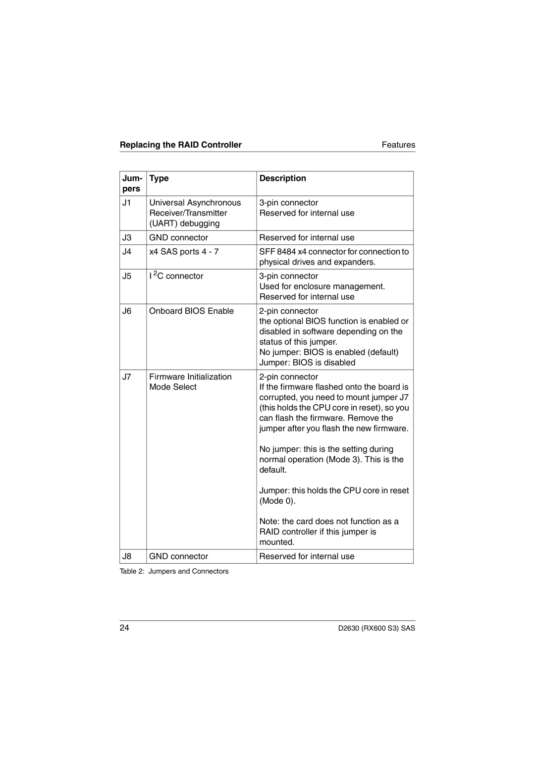
Table 2: Jumpers and Connectors
24 | D2630 (RX600 S3) SAS |
