MB3788
■HOW TO SET TIME CONSTANT FOR TIMER &
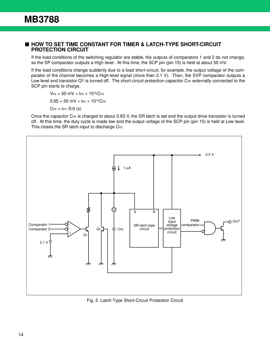
If the load conditions of the switching regulator are stable, the outputs of comparators 1 and 2 do not change, so the SP comparator outputs a High level. At this time, the SCP pin (pin 15) is held at about 50 mV.
If the load conditions change suddenly due to a load
VPE = 50 mV + tPE ⋅
0.65 = 50 mV + tPE ⋅
CPE = tPE /0.6 (s)
Once the capacitor CPE is charged to about 0.65 V, the SR latch is set and the output drive transistor is turned off. At this time, the duty cycle is made low and the output voltage of the SCP pin (pin 15) is held at Low level. This closes the SR latch input to discharge CPE.
|
|
|
|
|
|
| 2.5 V |
|
|
| 1 ∝A |
|
|
|
|
|
|
| 15 | R |
|
|
|
|
|
| S |
|
|
| |
|
|
|
|
| Low | PWM | OUT |
Comparator 1 | - |
|
|
| input | ||
| SR | voltage | comparator |
| |||
Comparator 2 | - | Q2 | CPE | circuit | protection |
|
|
| + | Q1 |
|
| circuit |
|
|
|
|
|
|
|
|
| |
2.1 V |
|
|
|
|
|
|
|
Fig. 5 Latch-Type Short-Circuit Protection Circuit
14