MB3788
■FUNCTIONAL DESCRIPTION
1. Major Functions
(1)Reference voltage power circuit
The reference voltage power supply produces a reference voltage (≈ 2.50 V) which is
(2)Error amplifier
The error amplifier detects the switching regulator output voltage and outputs a PWM control signal. It has a wide
Connecting the output pin and inversion input pin of the error amplifier through a feedback resistor and capacitor allows setting of any loop gain to provide stable phase compensation.
(3)PWM comparator
The PWM comparator controls the output pulse ON time according to the input voltage.
The voltage input to the
(4)Output circuit
The output circuit is configured in a
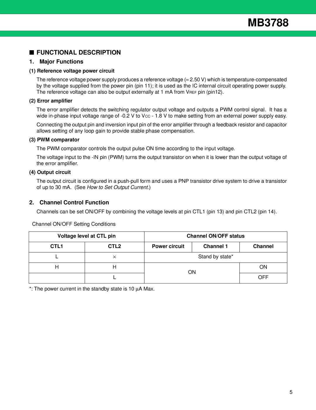
2. Channel Control Function
Channels can be set ON/OFF by combining the voltage levels at pin CTL1 (pin 13) and pin CTL2 (pin 14).
Channel ON/OFF Setting Conditions
Voltage level at CTL pin |
| Channel ON/OFF status |
| |||
|
|
|
|
|
|
|
CTL1 | CTL2 | Power circuit |
| Channel 1 |
| Channel |
|
|
|
|
|
|
|
L | ⋅ |
|
| Stand by state* |
| |
|
|
|
|
|
|
|
H | H |
| ON |
| ON | |
|
|
|
|
| ||
| L |
|
| OFF | ||
|
|
|
|
| ||
|
|
|
|
|
|
|
*: The power current in the standby state is 10 ∝A Max.
5