COMPONENT NAMES
MAIN UNIT
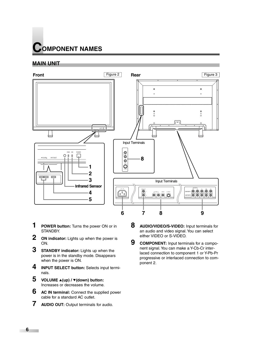
Front
Figure 2
Rear | Figure 3 |
Input Terminals
R
AUDIO
L
VIDEO2
8
Input Terminals
A C I N | AUDIO OUT |
L | AUDIO | VIDEO1 | |
| R | L |
|
R
COMPONENT 1
COMPONENT 2
![]() AUD IO
AUD IO ![]()
RL
R ![]()
![]() L
L
Y
Y
C b C r
P b ![]()
![]() P r
P r
| 6 | 7 | 8 | 9 | |
1 | POWER button: Turns the power ON or in | 8 | |||
2 | STANDBY. | an audio and video signal. You can select | |||
ON indicator: Lights up when the power is | either VIDEO or |
| |||
9 COMPONENT: Input terminals for a compo- | |||||
3 | ON. | ||||
STANDBY indicator: Lights up when the | nent signal. You can make a | ||||
laced connection to component 1 or | |||||
| power is in the standby mode. Disappears | ||||
| progressive or interlaced connection to com- | ||||
| when the power is ON. | ||||
4 | ponent 2. |
|
| ||
|
|
| |||
INPUT SELECT button: Selects input termi- |
|
|
| ||
5 | nals. |
|
|
| |
VOLUME K(up) / L(down) button: |
|
|
| ||
6 | Increases or decreases the volume. |
|
|
| |
AC IN terminal: Connect the supplied power |
|
|
| ||
7 | cable for a standard AC outlet. |
|
|
| |
AUDIO OUT: Output terminals for audio. |
|
|
| ||
6