Electrical Isolation of the MS-RA205
The
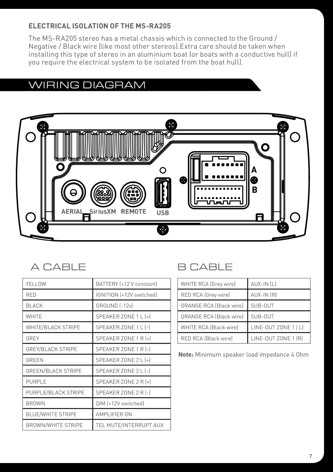
WIRING DIAGRAM
AERIAL SiriusXM REMOTE USB
A CABLE
YELLOW | BATTERY (+12 V constant) |
|
|
RED | IGNITION (+12V switched) |
|
|
BLACK | GROUND |
|
|
WHITE | SPEAKER ZONE 1 L (+) |
|
|
WHITE/BLACK STRIPE | SPEAKER ZONE 1 L |
|
|
GREY | SPEAKER ZONE 1 R (+) |
|
|
GREY/BLACK STRIPE | SPEAKER ZONE 1 R |
|
|
GREEN | speaker ZONE 2 L (+) |
|
|
GREEN/BLACK STRIPE | SPEAKER ZONE 2 L |
|
|
PURPLE | SPEAKER ZONE 2 R (+) |
|
|
PURPLE/BLACK STRIPE | SPEAKER ZONE 2 R |
|
|
BROWN | DIM (+12V switched) |
|
|
BLUE/WHITE STRIPE | AMPLIFIER ON |
|
|
BROWN/WHITE STRIPE | TEL MUTE/INTERRUPT AUX |
|
|
B CABLE
WHITE RCA (Grey wire) | |
|
|
RED RCA (Grey wire) | |
|
|
ORANGE RCA (Black wire) | |
|
|
ORANGE RCA (Black wire) | |
|
|
WHITE RCA (Black wire) | |
|
|
RED RCA (Black wire) | |
|
|
Note: Minimum speaker load impedance 4 Ohm
7